Elevator arrangement and method

a technology of elevators and movable ranges, applied in the direction of elevators, scaffold accessories, building scaffolds, etc., can solve the problems of affecting the safety of people and elevator components, affecting the movement range of elevator cars, and affecting the safety of elevator components, so as to achieve efficient and safe space and raise the moving range of elevator cars.

Active Publication Date: 2020-09-08
KONE CORP
View PDF16 Cites 1 Cited by
  • Summary
  • Abstract
  • Description
  • Claims
  • Application Information

AI Technical Summary

Benefits of technology

[0007]It is brought forward a new elevator arrangement, in particular a construction time elevator arrangement, comprising a hoistway; an elevator car mounted in the hoistway; a vertically movable support structure in the hoistway for supporting the elevator car, the movable support structure being mounted above the elevator car in the hoistway; the vertically movable support structure comprising a first working platform, having a planar working area, and a protective cover above the first working platform for protecting elevator components and / or people below it from falling objects, which protective cover covers most of the cross section of the hoistway. With this solution one or more of the above mentioned objects can be achieved. Particularly, the lower parts of the hoistway can thus be separated from the hoistway portion under construction simply, space efficiently and safely, the protection being flexible to use at all stages of a method aiming to raise the moving range of the elevator car. Preferable further details are introduced in the following, which further details can be combined with the elevator arrangement individually or in any combination.
[0015]In a preferred embodiment, protective cover comprises one or more displaceable cover parts forming part of the periphery of the protective cover, which displaceable cover parts are displaceable for reducing size of the protective cover and thereby for increasing free space beside the protective cover, in particular thereby creating a gap between the protective cover and an adjacent side wall of the hoistway. Hereby, the protective cover can be shifted into a state where it disturbs hoisting of the moveable support structure in the hoistway. Hoistway portion above the moveable support structure comprises components that could otherwise be at risk of being hit by parts of the protective cover. The presented solution facilitates tight protective coverage during use of the elevator car for transporting and hoisting thereof with sufficient clearance relative to stationary elevator components, such as guide rails of the elevator car for instance.
[0017]In a preferred embodiment, the one or more displaceable cover parts include a displaceable cover part extending between the first side wall and the first guide rail covering at least part of the gap formed between the first side wall and the first guide rail. The one or more displaceable cover parts preferably moreover include a displaceable cover part extending between the second side wall and the second guide rail and covering at least part of the gap formed between the second side wall and the second guide rail. Displaceabitily of the cover part(s) positioned like this allows tight protection of the hoistway while allowing also free hoisting of the vertically moveable support structure in cases where guide rails are supported on a hoistway wall with brackets extending across the space between the guide rail and a hoistway wall.
[0020]In a preferred embodiment, the one or more displaceable cover parts are displaceable cover plates. Generally, the displaceable cover parts are preferably rigid parts. They can be made of metal, which is simple and cheap, or alternatively they can have a sandwich structure comprising metal and / or non-metallic material. The sandwich structure facilitates impact absorbing properties of the displaceable cover parts.
[0042]In a preferred embodiment, the method comprises after said using and before said hoisting, displacing one or more displaceable cover parts of the protective cover for reducing size of the protective cover, and in particular for increasing free space beside the protective cover, in particular thereby creating a gap between the protective cover and adjacent side wall(s) of the hoistway.

Problems solved by technology

In this the elevator arrangements as described above, construction of the upper part of the elevator shaft and installation of elevator components in the shaft can be a safety risk for the people and elevator components.
Objects, such as installation tools or construction parts, can fall from the upper parts of the hoistway, and hit and damage people or elevator components.
A drawback of this solution has been that it has been inflexible to use as the mounting of the support structure has required time, a certain hoistway structure and space in the hoistway.

Method used


Image

  • Elevator arrangement and method
  • Elevator arrangement and method
  • Elevator arrangement and method

Examples


Embodiment Construction

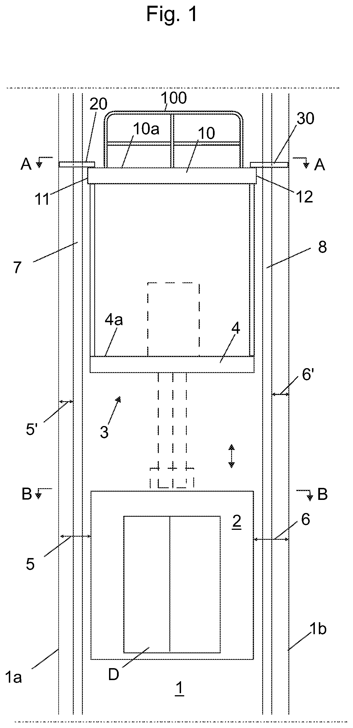
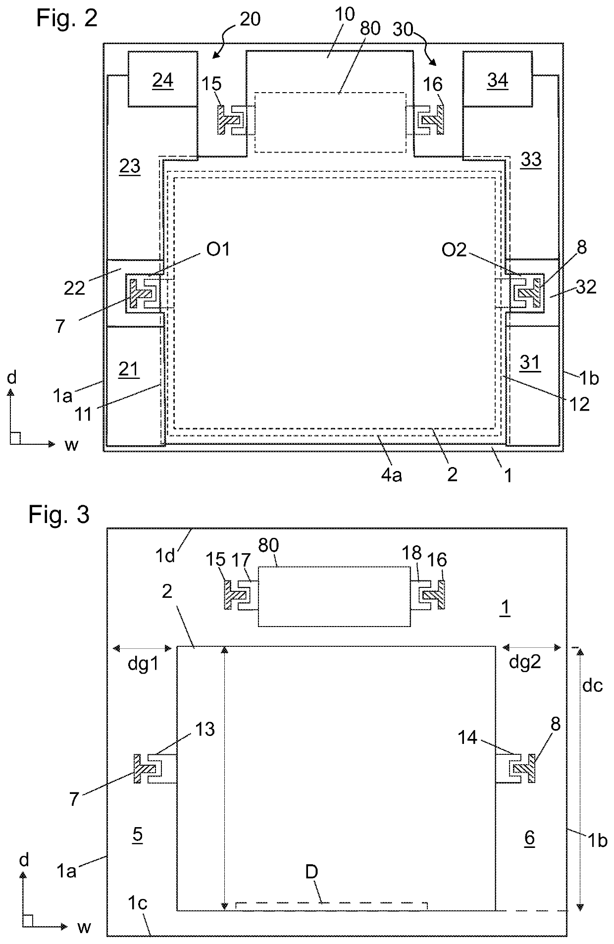
[0061]FIG. 1 illustrates a preferred embodiment of an elevator arrangement, in particular a construction time elevator arrangement. FIGS. 2 and 3 illustrate cross sections A-A and B-B of FIG. 1, respectively. The elevator arrangement presented comprises a hoistway 1 formed inside a building, an elevator car 2 mounted in the hoistway 1, and a vertically movable support structure 3 in the hoistway 1 supporting the elevator car 2. The movable support structure 3 is in FIG. 1 mounted above the elevator car 2 in the hoistway 2 stationarily by mounting means (not showed), which are releasable so as to enable unblocked hoisting of the movable support structure 3 in the hoistway 1. Said mounting means can be any kind suitable for purpose, e.g. any kind known from prior art, such as retractable support beams, for example. Vertical movability of the support structure 3 provides that the moving range of the elevator car can be stepwise extended to reach higher in the hoistway 1, the elevator a...


PUM


Abstract

An elevator arrangement, in particular a construction time elevator arrangement, includes a hoistway; an elevator car mounted in the hoistway; and a vertically movable support structure in the hoistway for supporting the elevator car, the movable support structure being mounted above the elevator car in the hoistway. The vertically movable support structure includes a first working platform, having a planar working area, and a protective cover above the first working platform for protecting elevator components and / or people below it from falling objects. The protective cover covers most of the cross section of the hoistway.

Description

FIELD OF THE INVENTION[0001]The invention relates an elevator arrangement and a method, and particularly to construction time protection of persons and / or components located in a lower portion of a hoistway of an elevator.BACKGROUND OF THE INVENTION[0002]In connection with so-called jump-lifts, the bottom part of an elevator hoistway is taken into use before the building has been completed. In this case the upper parts of the building as well as the top part of the elevator hoistway can be constructed at the same time as an elevator moving in the bottom part of the elevator hoistway already serves people on the lower floors of the building. Generally in jump-lifts the elevator car moving in the lower parts of the elevator hoistway is supported and moved during construction-time use with a hoisting machine supported on a vertically movable support structure in the elevator hoistway. The installation work in the upper parts of the elevator hoistway above this vertically movable suppor...

Claims


Application Information

Patent Timeline
Patent Type & Authority Patents(United States)
IPC IPC(8): B66B11/00B66B9/00E04G3/28B66B19/00E04G5/14E04G21/32E04G3/24
CPCB66B19/00E04G5/14E04G3/24E04G21/32E04G3/28B66B9/00B66B11/0005E04G2003/286B66B5/005
Inventor HÄGG, JORICIUCULESCU, GABRIEL
Owner KONE CORP
Why Eureka
Try Eureka