
Camouflage laminate with field-adaptable visual and IR signature management

a technology of visual and ir signature management and camouflage laminate, which is applied in the field of camouflage, can solve the problems of increasing difficulty in successfully camouflage covert objects, increasing difficulty in avoiding detection of covert ground-based objects from above, and threats that are not adequately addressed by current camouflage approaches

Active Publication Date: 2020-09-08
WARWICK MILLS INC
View PDF15 Cites 1 Cited by
  • Summary
  • Abstract
  • Description
  • Claims
  • Application Information

AI Technical Summary

Benefits of technology

The patent describes a camouflage system that can be adjusted to match different vegetation backgrounds without needing multiple camouflage covers. The camouflage cover mimics the spectral signature of surrounding vegetation in both visible and infrared wavelengths. Additionally, the camouflage has radar-absorbing and scattering properties, as well as features to manage solar gain and reduce heat load. The patent also includes UV reflectors to manage solar gain and electromagnetic shielding. Overall, the invention helps to avoid detection by LIDAR and provides field-adaptable control for managing the camouflage's visual and IR spectral signature.

Problems solved by technology

Advances in various method of detection have made it increasingly difficult to successfully camouflage covert objects.
In particular, the development and proliferation of advanced ground-observation and ground-scanning technologies has made it increasingly difficult to avoid detection of covert ground-based objects from above.
Threats that are not adequately addressed by current camouflage approaches include advanced radar methods such as Side Aperture Radar (SAR) and the laser range finding analog of radar known as “LiDAR,” as well as apparatus that detect EM signatures emitted by communications equipment and other electronic devices.
This can be a burdensome requirement, which is rendered even more costly and bulky when the camouflage covers also include vascular systems for heat shielding.
Unfortunately, even when a variety of different camouflage covers are provided, it is inevitable that vegetative environments will be encountered for which none of the provided covers provides an ideal match to the surrounding colors and patterns.
As a result, in a growing number of hostile situations it is no longer sufficient for camouflage to simply mask heat emissions and match the surrounding colors and visual patterns, because hostile forces are able to use this new instrumentation to detect differences and variations in the infrared (“IR”) and ultraviolet (“UV”) absorptions and emissions in a scene as a function of IR and UV wavelength.
It is not yet practical to use interferometric instruments such as FTIR laboratory spectrometers for spatial remote sensing.
These differences between the spectral signatures of different vegetative environments increase the challenge and the importance of accurately matching camouflage to the spectral signature of the specific vegetative environment in which it is used.

Method used


Image

  • Camouflage laminate with field-adaptable visual and IR signature management
  • Camouflage laminate with field-adaptable visual and IR signature management
  • Camouflage laminate with field-adaptable visual and IR signature management

Examples


Embodiment Construction

[0134]The present invention is a camouflage signature management system and method that provide field-adaptable control for managing the visual and IR spectral signature displayed by a camouflage cover, so that the displayed signature can be adapted to emulate a variety of different vegetation background environments without requiring multiple, redundant camouflage covers.

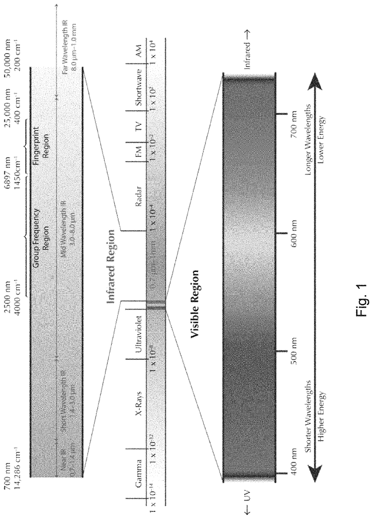
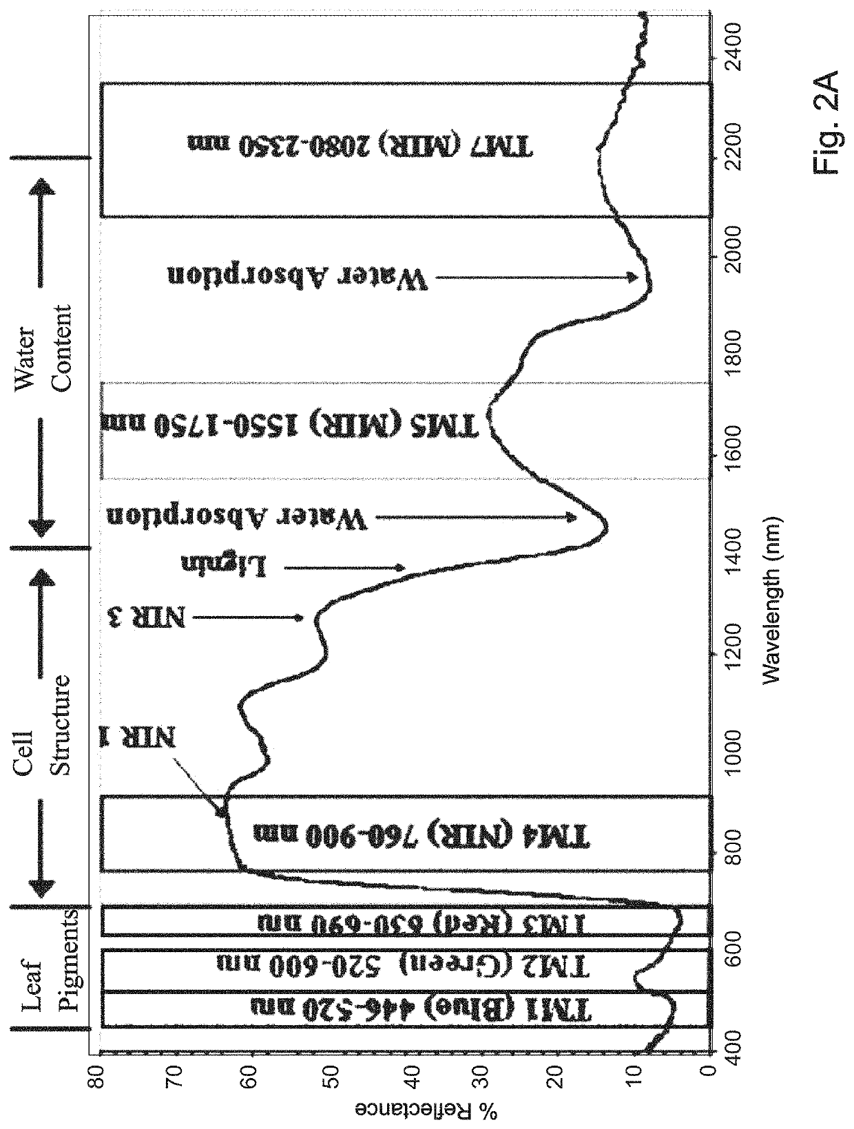
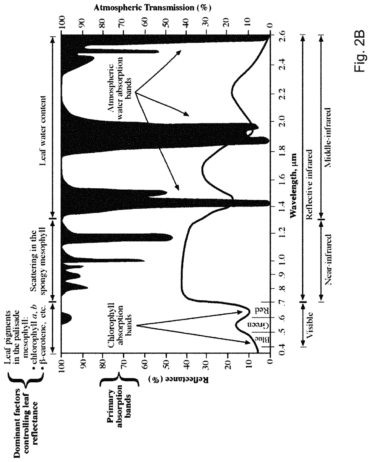
[0135]The disclosed system is configured in several aspects to emulate the chemical and physical properties of vegetation, and thereby to emulate the natural spectral signatures of vegetation. As used herein the term “spectral signature” refers to the degree to which the vegetative background, and / or the disclosed camouflage cover, absorbs and reflects light as a function of the wavelength of the light (which is sometimes reported in equivalent units of frequency or wave number), over the visible and IR regions of the electromagnetic spectrum. Embodiments of the disclosed camouflage cover also includes printed patt...


PUM

PropertyMeasurementUnit
temperatureaaaaaaaaaa
surface energyaaaaaaaaaa

Abstract

A camouflage system adaptively matches the visible and IR spectrum of surrounding vegetation. A bio-chromophore dye solution circulated through an upper channel and distributed by a pulp or fabric matches the visible and biological IR spectrum, while water evaporated from the upper channel or from a separate lower channel matches the water IR spectrum. Dye can be retained in the pulp or continuously circulated. Permanently printed colors and / or patterns can also be included. Petalation cooperative with a channel flow pattern can release evaporated water and inhibit LiDAR detection. An upper waxy layer and surface embossing can avoid specular reflections. The camouflage signature can be compared with the environment and automatically adjusted as needed. Embodiments include thermal management, electromagnetic shielding, and / or radar scattering / absorbing subsystems. An airbag ground plane can match a terrain contour and avoid LiDAR detection. Multiple zones can provide adaptive display of visible and IR patterns.

Description

COPYRIGHT NOTICE[0001]A portion of the disclosure of this patent document contains material that is subject to copyright protection. The copyright owner has no objection to the facsimile reproduction by anyone of the patent document or the patent disclosure, as it appears in a published Patent and Trademark Office patent file or record, but otherwise reserves all copyrights whatsoever.RELATED APPLICATIONS[0002]This application claims the benefit of U.S. Provisional Application No. 62 / 384,334, filed Sep. 7, 2016, U.S. Provisional Application No. 62 / 481,417, filed Apr. 4, 2017, and U.S. Provisional Application 62 / 527,723, filed Jun. 30, 2017, all of which are herein incorporated by reference in their entirety for all purposes.FIELD OF THE INVENTION[0003]The invention relates to camouflage, and more particularly, to camouflage that protects objects from visual and infrared detection.BACKGROUND OF THE INVENTION[0004]Camouflage, which can be broadly defined as apparatus and methods for p...

Claims


Application Information

Patent Timeline
Patent Type & Authority Patents(United States)
IPC IPC(8): F41H3/02B32B27/12B32B5/26B32B21/08B32B27/34B32B3/20B32B21/04B32B27/14B32B5/02B32B3/02B32B5/30B32B7/12B41M3/06B32B27/36B32B5/16
CPCF41H3/02B32B21/08B32B5/022B32B3/20B32B27/36B32B5/26B32B21/04B32B7/12B41M3/06B32B5/30B32B3/02B32B27/34B32B5/16B32B27/14B32B27/12B32B2255/205B32B2250/05B32B2255/10B32B2571/00B32B2255/02B32B2262/062B32B2307/7265B32B2260/04B32B2262/067B32B2262/0284B32B2307/212B32B2262/04B32B2260/025B32B2367/00B32B2307/41B32B2255/24B32B2307/412B32B2307/302B32B2307/4026B32B2250/03B32B2307/726B32B2262/0261B32B2459/00B32B3/266B32B3/08B32B3/085B32B2307/4023B32B2307/40B32B7/02B32B7/09B32B23/10B32B2307/724B32B27/08B32B27/16B32B3/28
Inventor HOWLAND, CHARLES A
Owner WARWICK MILLS INC
Learn More