Depolarizers

a depolarizer and polarizer technology, applied in the field of depolarizers, to achieve the effect of avoiding polarization mixing and cross-coupling

Active Publication Date: 2020-10-20
EXALOS
View PDF25 Cites 2 Cited by
  • Summary
  • Abstract
  • Description
  • Claims
  • Application Information

AI Technical Summary

Benefits of technology

[0027]A depolarizer of this kind is able to achieve low DOP performance over a wide spectral range. In the proposed design, the power splitter splits the optical signal without regard to the input polarization, so is fundamentally different from designs which use a polarizing beam splitter at the input to separate out the two polarization states of an essentially depolarized input beam into two arms. Moreover, in comparison to existing designs based on a feedback loop, the proposed design provides for lower insertion losses and therefore higher output power. For example, the loopback architectures of U.S. Pat. No. 6,760,495 B2 by Gonthier et al or of U.S. Pat. No. 6,735,350 B1 by Gauthier are based on a 50:50 splitter where one optical output is looped back, while rotating the polarization, and mixed with the input light. These prior art architectures intrinsically have a minimum insertion loss of 50%. By contrast, with our feedforward design in which two parallel beams propagate in a forward direction, reminiscent of a Mach-Zehnder interferometer (MZI) structure, and in which the light source generates light with a high PER, the minimum insertion loss is in theory zero, and in practice can be limited to around 1 dB.
[0050]A further aspect of this invention covers the realization of such a depolarizer using a photonic integrated circuit (PIC) to accommodate some or all of its optical components, in order to significantly reduce the depolarizer's size.

Problems solved by technology

The problem here is that spinning the fiber causes birefringence, which may result in various problems if the (broadband) light source is not depolarized.
While all-fiber Lyot depolarizers of this kind work well for narrowband light sources such as lasers they have some limitations for broadband light sources, such as SLEDs, where the DOP performance is not spectrally flat, but shows spectral modulations with some wavelength regions having high DOP values and others in between lower DOP values.

Method used


Image

  • Depolarizers
  • Depolarizers
  • Depolarizers

Examples


Embodiment Construction

lass="d_n">[0079]Before describing various embodiments, we first describe the meaning of some terms used in this document.

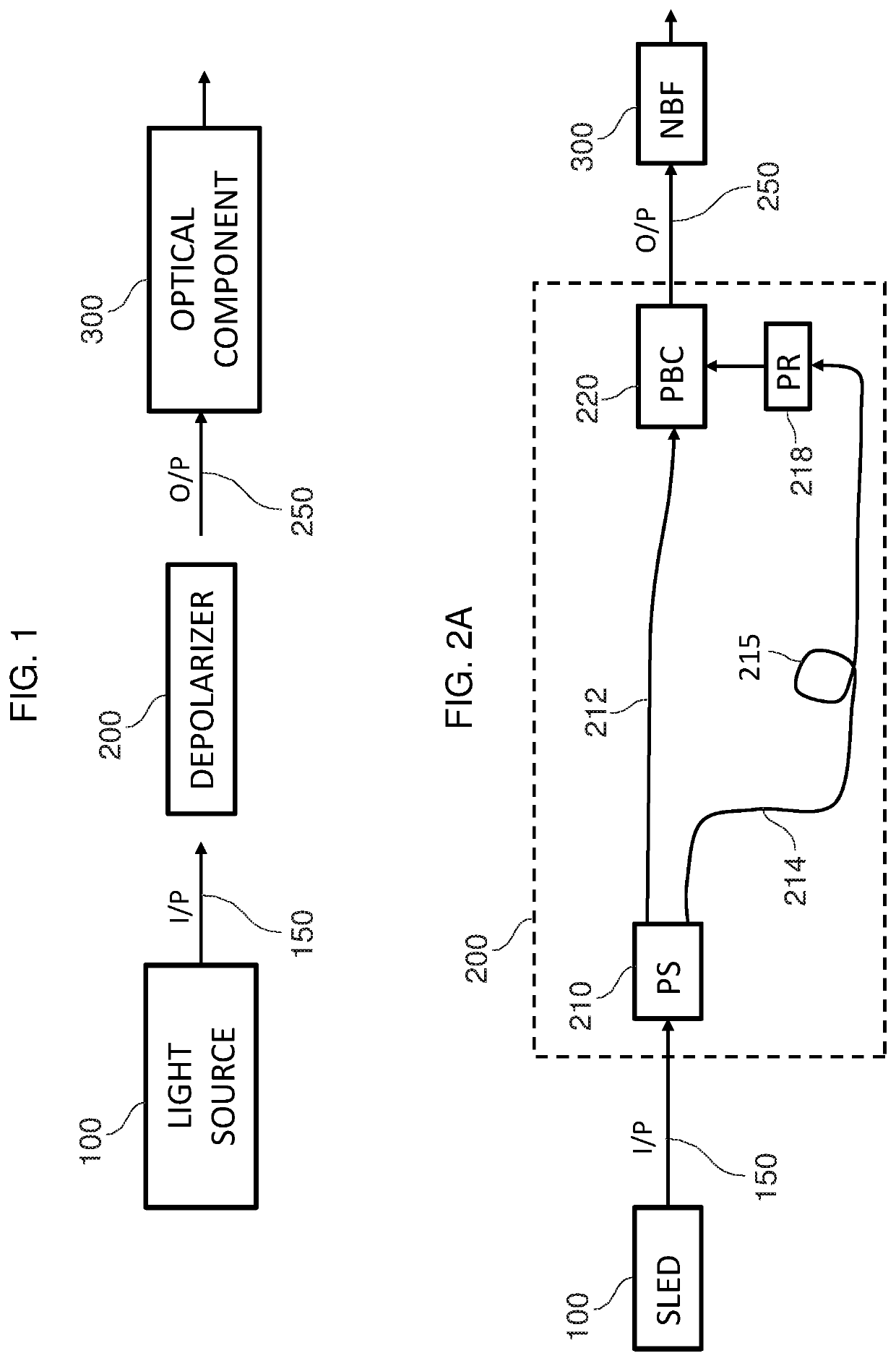
[0080]Optical component: The term optical component is used generically to include all components relevant for the optical design and performance of a device or system, including for example optoelectronic components (e.g. a photodiode or a variable optical attenuator) and optomechanical components (e.g. coupler positioners) and not just purely optical components (e.g. a micro-optic lens or a section of optical fiber). An optical component may include a single optical element or a plurality of optical elements.

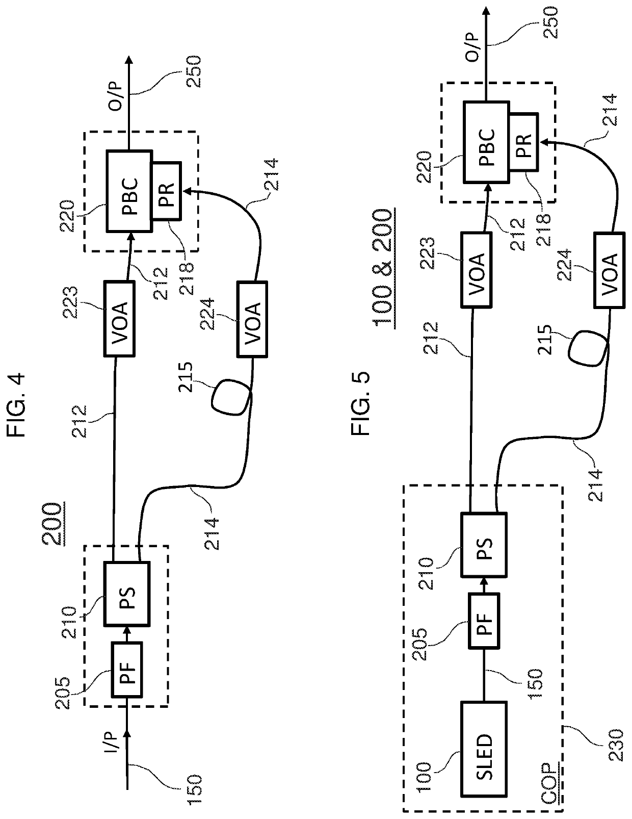
[0081]Common optical package (COP): COP is a term used to describe physical packaging available to house one or more optical components as well as optionally also electronic components. A COP is characterized by a housing containing the components to be packaged and externally connectable electrical pins and / or optical outputs, such as for connecting optica...


PUM

PropertyMeasurementUnit
wavelength rangeaaaaaaaaaa
insertion lossaaaaaaaaaa
coherence lengthaaaaaaaaaa

Abstract

A depolarizer for a broadband optical source to split the source beam by power, not by polarization state, and route the components into respective light paths. A polarization rotator arranged in one of the light paths rotates the polarization state of that beam component to make it orthogonal to that of the other. The components are then recombined by a combiner and output. A variable optical attenuator is arranged in one of the light paths, which during operation is adjusted by a controller to maintain power equalization between the light paths and hence depolarization performance. The controller receives power measurements from the light paths and from after the combiner via respective sensors. With this feedforward design reminiscent of a Mach-Zehnder interferometer the light from a light source which generates highly polarized light can be depolarized in theory with zero insertion loss and in practice with losses of about 1 dB.

Description

CROSS-REFERENCE TO RELATED APPLICATIONS[0001]This non-provisional patent application claims the benefit of and priority to U.K. Patent Application No. 1714525.1, filed Sep. 8, 2017, which is incorporated herein by reference in its entirety.STATEMENT REGARDING FEDERALLY SPONSORED RESEARCH OR DEVELOPMENT[0002]Not ApplicableREFERENCE TO SEQUENCE LISTING, A TABLE, OR A COMPUTER PROGRAM LISTING COMPACT DISC APPENDIX[0003]Not ApplicableFIELD OF THE INVENTION[0004]The invention relates to a depolarizer for generating a depolarized output from a polarized input received from a light source, more especially but not exclusively when the light source is a broadband light source.BACKGROUND[0005]Certain applications, such as optical component testing, fiber optic gyroscopes (FOGs), fiber optic current sensors (FOCS), fiber Bragg grating (FBG) interrogation and certain medical applications, require broadband input light that is substantially free of polarization, i.e. has a low degree of polariza...

Claims


Application Information

Patent Timeline
Patent Type & Authority Patents(United States)
IPC IPC(8): G02B27/28G02F1/01F21V8/00G02B6/27G02B6/122G02B27/10G02B6/126G02B6/28G02B6/26G02B6/42
CPCG02F1/0136G02B6/0006G02B27/1006G02B27/283G02B6/2786G02B6/122G02F2001/0139G02B6/2706G02B6/4213G02B6/2793G02B6/2843G02B6/266G02B6/126G02F1/0139G02B6/274
Inventor DÜLK, MARCUSVORREAU, PHILIPP
Owner EXALOS
Why Eureka
Try Eureka