Air cart product flow condition monitoring

a technology of product flow and air cart, which is applied in the direction of agriculture gas emission reduction, fertilising methods, agriculture, etc., can solve the problems of user air waste and system blockage, and achieve the effect of effective control of air sources, greater sensitivity, and diameter of product distribution lines

Active Publication Date: 2020-11-03
CNH IND CANADA
View PDF29 Cites 0 Cited by
  • Summary
  • Abstract
  • Description
  • Claims
  • Application Information

AI Technical Summary

Benefits of technology

[0005]The present inventors have recognized that a pressure gradient or differential in a product distribution line for conveying granular particulate material, such as seed or fertilizer, in an air flow to an agricultural field consistently decreases as air speed (velocity) in the product distribution line decreases until a critical air speed is reached. Below the critical air speed, the particulate material may become susceptible to falling out of the air flow to potentially cause a blockage in the system. Accordingly, pressure sensors arranged in the product distribution line can be monitored for effectively controlling an air source producing the air flow. In one aspect, a diameter of the product distribution line can increase between upstream and downstream locations for monitoring with even greater sensitivity.
[0006]In one aspect, total pressure drop and local pressure drops in specific locations can be monitored along the path of the hose. The monitored data can be interpreted for control of an air source. Also, the hose routing can be physically manipulated to respond more quickly by increasing the diameter of a section of the hose (up to 15% larger) before any bend or even a straight section. By measuring the local pressure drop from an upstream point to a point on the larger diameter region the trend that appears can give an earlier indication that product may start falling out of the airstream before it actually happens. As seeding tool widths get larger and conveying lines get longer it may become even more beneficial to monitor product flow status in these lines. Longer lines may also require higher air velocity to move product effectively. Standard practice is to do a “fountain test” to ensure a 12-24 inch fountain of product is exiting one of the hoses at an opener on the outer section to set the air flow. Users who do not do this can instead simply set their fan at a significantly high rate so that the system never becomes blocked. However, with the increasing use of variable product application rates across the tool (varying seed and / or fertilizer rates according to a prescription map) a user may be wasting air. The present invention provides a system for monitoring the status of the product flow in the airstream to match the fountain test, or potentially even lower, to avoid blockages by controlling the fan based on the product rate. The system can utilize at least one local pressure measurement region, preferably at a known “high” pressure drop location, to act as an early warning monitor of the product flow status before the critical air speed is reached. The system can also utilize pressure taps so the total pressure drop can be monitored. A slight increase in hose diameter (on the order of 5-20%) over the designated local pressure region can help give provide an early predictive characteristic.
[0007]As a result, the fan can safely operate at a lower air speed, because the flow monitoring of the local regions gives early warning well before settling of product happens in the line. With the fan running safely at lower speeds, power savings can be realized in the system. Also, safer conveying conditions for seeds (reducing or eliminating damage) and fertilizer (reducing damage in the conveying line) can be achieved. Lower exit velocities into furrow also yields a higher probability that more product will end up where desired and be less susceptible to bouncing out of the soil furrow.
[0012]In another aspect, changes in cross-sectional dimensions of a pneumatic conveying pipe / hose can be used to determine if deviations from a current state of a pneumatic conveying system will increase the risk of plugging the system. By applying an effect in which changes in cross-sectional diameter have on flow conditions, a control system can be applied to a candidate region of the pneumatic conveying system. A set-point determined from the automatic fan control calibration procedure above can then be used to inform the set-point for controlling the fan. This may eliminate a need for the operator- or factory-determined safe operating points to be pre-determined. Thus, after a system state diagram is created from a calibration method, an auto fan control method can simply follow a system state diagram to ensure the system operates in an efficient range. This range can be as low as the pressure minima or as high as the known fountain test set point as desired. In making the seeding system self-learning, utilizing the auto calibration procedure with the flow monitoring procedure, the system can determine where the pressure minima is for each product and be able to predict well in advance before arrival in the pressure minima region. Increasing product mass rate will shift the curves up and to the right slightly, but this can be established with the auto calibration procedure so the fan control can follow the state diagram for safe and efficient conveying. This type of control system may be advantageous when used with fully or autonomous seeding systems.

Problems solved by technology

Below the critical air speed, the particulate material may become susceptible to falling out of the air flow to potentially cause a blockage in the system.
However, with the increasing use of variable product application rates across the tool (varying seed and / or fertilizer rates according to a prescription map) a user may be wasting air.

Method used


Image

  • Air cart product flow condition monitoring
  • Air cart product flow condition monitoring
  • Air cart product flow condition monitoring

Examples


Embodiment Construction

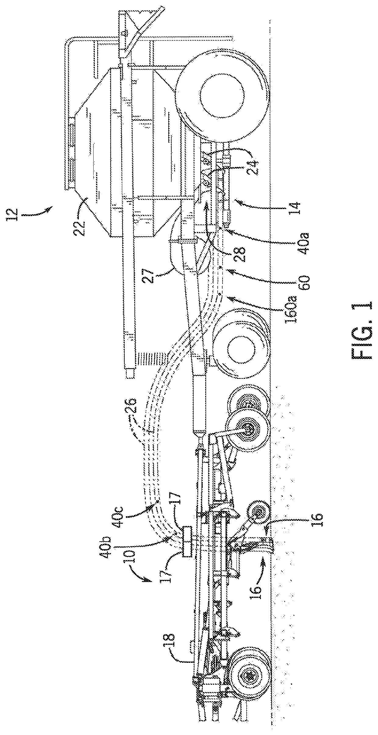
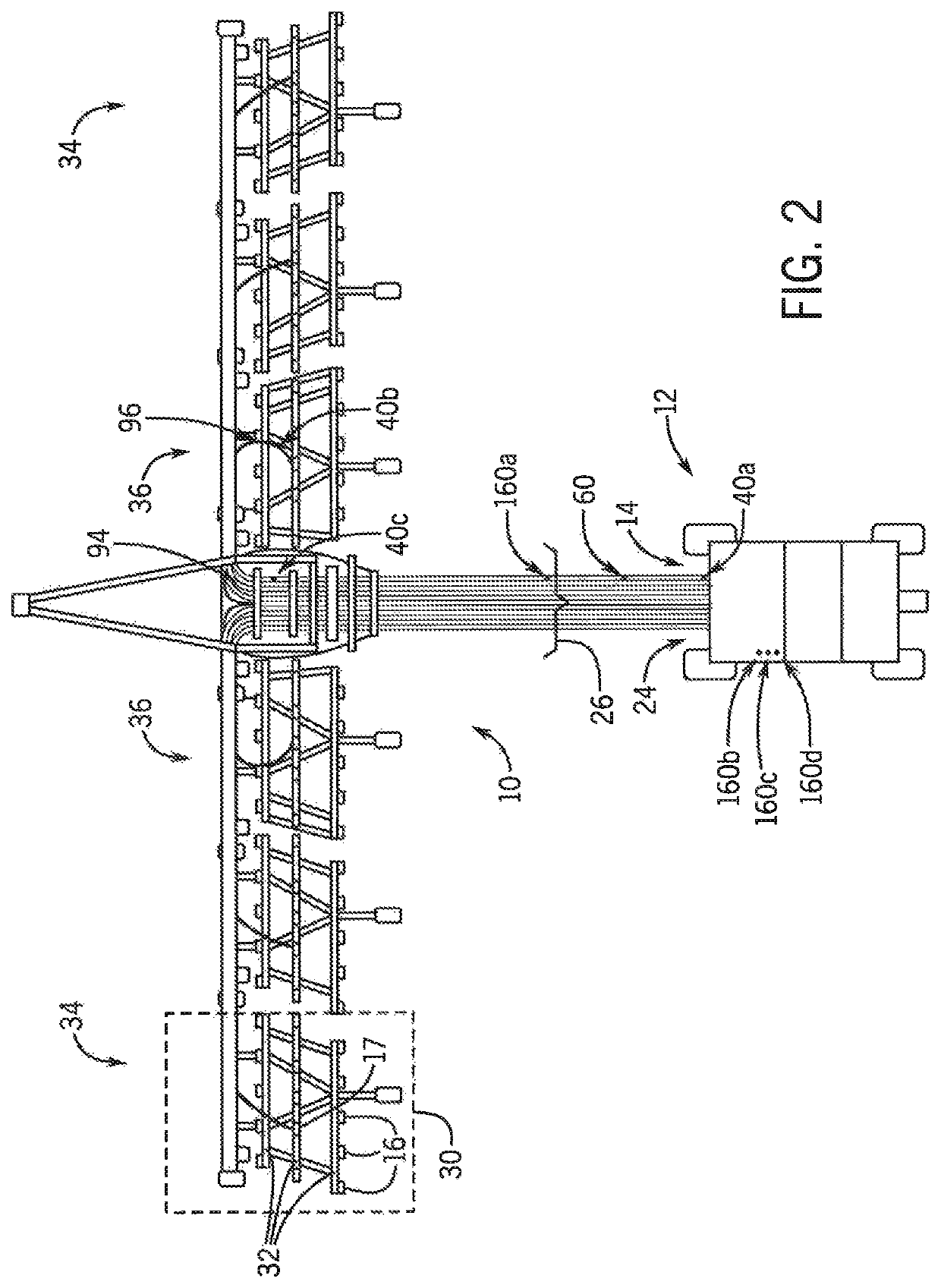
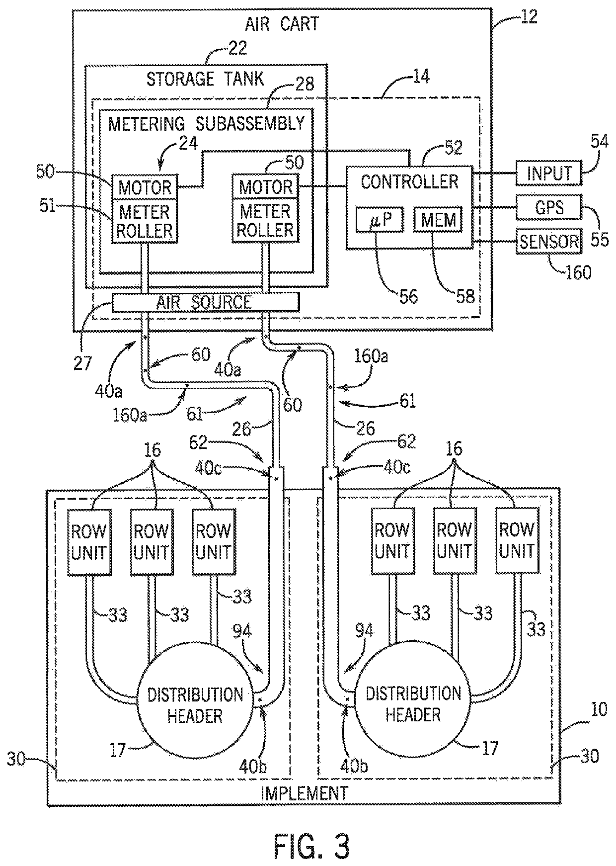
[0024]Referring now to the drawings and specifically to FIG. 1, a side view of an exemplar agricultural implement 10, which may be a seeding implement or tool, coupled to an air cart 12 having a control system 14 is provided in accordance with an aspect of the invention. The implement 10 includes multiple row units 16 and multiple distribution headers 17 supported by a frame 18. Each distribution header 17 is configured to receive agricultural particulate material, such as seed or fertilizer, from the air cart 12, and to route the product to each row unit 16. The row units 16, in turn, may be configured to deposit the agricultural product onto the soil as the implement 10 travels across an agricultural field. As shown, the air cart 12 can be coupled to the implement 10 via the frame 18. The air cart 12 may include one or more product storage tanks 22 configured to store one or more agricultural products (particulate material). Each product storage tank 22 is coupled to a correspondi...


PUM


Abstract

A pressure gradient or differential in a product distribution line for conveying granular particulate material, including at least one of seed or fertilizer, in an air flow to an agricultural field consistently decreases as air speed and velocity in the product distribution line decreases until a critical air speed is reached. Below the critical air speed, the particulate material is susceptible to falling out of the air flow to cause a blockage in the system. Pressure sensors arranged in the product distribution line are monitored for effectively controlling an air source producing the air flow. A diameter of the product distribution line increases between upstream and downstream locations for monitoring with greater sensitivity.

Description

FIELD OF THE INVENTION[0001]The present invention relates generally to systems for distributing particulate material to agricultural fields, and more particularly, to such systems having pressure sensors in product distribution lines for conveying the particulate material in which pressure gradients calculated form the pressure sensors are used to control an air source to increase or decrease the air flow in response to a change in the pressure gradient.BACKGROUND OF THE INVENTION[0002]Generally, a tractor or work vehicle tows seeding or fertilizing implements via a hitch assembly that connects to a rigid frame of a planter, seeder or fertilizer applicator. These crop production systems typically include one or more delivery lines that carry particulate material, such as seed or fertilizer. In certain systems, ground engaging tools are used to break the soil to deposit the particulate material carried by these delivery lines. After depositing the particulate material, each ground en...

Claims


Application Information

Patent Timeline
Patent Type & Authority Patents(United States)
IPC IPC(8): A01C7/08A01C7/20A01C21/00A01C7/10
CPCA01C21/005A01C7/105A01C7/205A01C7/084A01C7/081A01C15/04A01C7/102Y02P60/21
Inventor GERVAIS, JOELPAULSON, IANMITTAL, LAVNOBLE, SCOTT
Owner CNH IND CANADA
Why Eureka
Try Eureka