Utility receptacle shielding insert

a technology for receptacles and inserts, which is applied in the field of accessories, can solve the problems of less than ideal finish around the receptacle, unwide acceptance of devices in the trade, and tedious and time-consuming jobs, and achieves the effects of convenient production, compact storage and transportation, and low cos

Active Publication Date: 2020-11-03
IMAGINE ENTERPRISES OF COLORADO LLC
View PDF20 Cites 0 Cited by
  • Summary
  • Abstract
  • Description
  • Claims
  • Application Information

AI Technical Summary

Benefits of technology

[0005]This invention provides a shielding insert (hereinafter variously referred to as an insert, unit or shield) to mask, or shield, the opening of a recessed light fixture or other recessed utility receptacle typically located through walls or ceilings of various buildings from material contamination during construction, including surface treatment of the adjacent wall or ceiling. The shield is removably locatable by inserting it into the receptacle opening and is flush with the surface where the opening is defined once positioned. The insert can be manufactured from plastic, metal or molded pulp product for washing and reuse, or paperboard, cardboard, or molded pulp product for either reusable or disposable use. The insert is inexpensive to produce, is compact for storage and transport, can be conveniently produced in a number of sizes and configurations, is secure once installed, is easily removed when wall or ceiling treatment is complete, and requires no special tools or fasteners for use.
[0009]It is therefore an object of this invention to provide an insert for shielding the interior of a recessed light fixture or other recessed utility receptacle from material contamination during surface treatment of the adjacent wall or ceiling.
[0011]It is still another object of this invention to provide an insert for shielding the interior of a utility receptacle that can be manufactured for reuse or disposal and that is stackable.
[0012]It is yet another object of this invention to provide a shielding insert for utility receptacles that is inexpensive to produce, is convenient to store and transport, is secure once installed and easily removed when wall or ceiling treatment is complete, and that requires no special tools or fasteners for use.

Problems solved by technology

This job is tedious and time consuming and often results in less than ideal finish around the receptacle (from uneven covering or cracking and peeling of finish during tape removal for example).
Such devices have not found wide acceptance in the trades, however, likely due to expense of production and tooling and / or ongoing expense for fasteners, specialty tools and restocking.
Many, including those requiring specialty tools and fasteners, present a storage and transport problem for installers, for example not being conveniently stackable for transport to or between job sites.
Moreover, some heretofore suggested devices may not remain secure during finishing treatments, particularly where surfaces remain wet, and / or the devices present protruding portions extending away from the surface thereby imposing undesirable surface characteristics, such as impediments and incongruities, for finishers during treatment applications.
Moreover, where the receptacle openings are relatively large, and particularly where the openings are curved, such as is common with recessed light fixture receptacles (for example, fixtures receptacles having a cylindrical opening portion and commonly referred to as “can lights”), securement and retention of such devices becomes difficult.
These difficulties have not been overcome heretofore.

Method used


Image

  • Utility receptacle shielding insert
  • Utility receptacle shielding insert
  • Utility receptacle shielding insert

Examples


Embodiment Construction

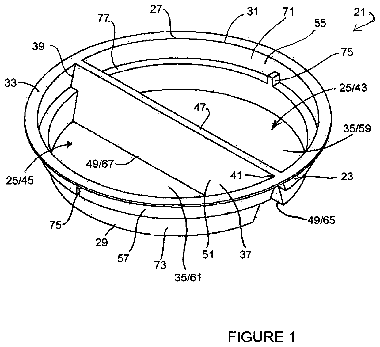
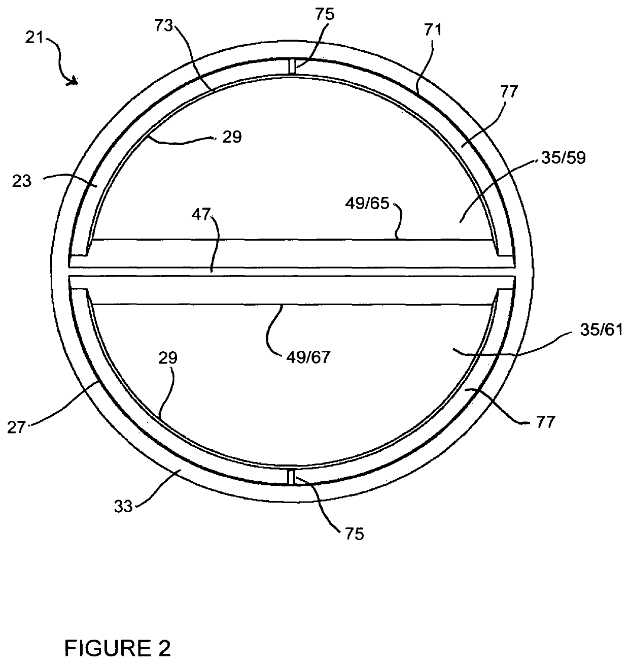
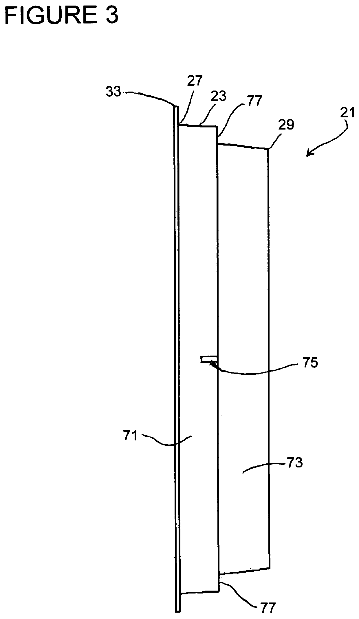
[0026]A first construction 21 of the preferred embodiment of the shielding insert of this invention is shown in FIGS. 1 through 4, this construction being particularly suitable for manufacture from plastic, metal, or other washable and reusable materials. The insert shown in the FIGURES is adapted for use with receptacles for recessed lighting fixtures (can light fixtures, for example), and is removably insertable into the body of the receptacle to keep material out during construction, wall treatment and the like. Other configurations adapted for use with different utility receptacles or different receptacle sizes can be provided which utilize the teachings of this disclosure, and thus are deemed to be within the scope of the invention claimed herein.

[0027]Shielding insert 21 is preferably a monolithic unit (molded for example). The unit includes an outer wall 23 defining an interior area 25. Outer wall 23 is defined between first and second spaced bounds 27 and 29 (the extents of ...


PUM


Abstract

A stackable shield removably insertable in an opening to an interior of a recessed light fixture receptacle is disclosed. The unit is characterized by a v-shaped divider structure defined by first and second divider walls extending between opposite parts of the outer wall. Configuration of the outer wall is alterable by urging the divider walls toward one another.

Description

FIELD OF THE INVENTION[0001]The invention relates to accessories for use during application of ceiling or wall finishing treatments such as dry wall compound (or mud), plaster, paint or the like, and, more particularly, relates to devices for shielding during such application receptacles accommodating electrical, heating and / or plumbing utilities commonly located through the surface of walls and ceilings.BACKGROUND OF THE INVENTION[0002]Utility receptacles of various kinds are installed during construction of buildings to accommodate location of services thereat such as lights and electrical controls, heating and plumbing and related controls, and a variety of other utilities such as communications and safety equipment. These receptacles must remain accessible through the walls and ceilings after the walls and ceilings are finished, whereupon the utilities and controls, finish panels and the like are installed. To prevent the receptacles from becoming contaminated with the various f...

Claims


Application Information

Patent Timeline
Patent Type & Authority Patents(United States)
IPC IPC(8): B05B12/26B05C21/00E04G23/02B05B12/24B05D1/32
CPCB05C21/005B05B12/26E04G23/0207B05D1/32B05B12/24
Inventor LUJAN, CHARLES A.ANGSTEAD, RONALD A.
Owner IMAGINE ENTERPRISES OF COLORADO LLC
Why Eureka
Try Eureka