
Methods of producing slanted gratings with variable etch depths

Active Publication Date: 2020-11-03
APPLIED MATERIALS INC
View PDF2 Cites 3 Cited by
  • Summary
  • Abstract
  • Description
  • Claims
  • Application Information

AI Technical Summary

Benefits of technology

This disclosure provides a method for making a diffracted optical element by creating an optical grating layer over a substrate and patterning a hardmask over it. There is then a sacrifice layer that is made on top of the hardmask, which has a non-uniform height. This non-uniform height causes the optical grating to have different depths in different areas. This allows for better control over the diffraction of light and makes it easier to create more complex optical elements.

Problems solved by technology

Unfortunately, current approaches of forming optical gratings with varied heights, widths, and / or shapes across diffracting and viewing fields have proved challenging.

Method used


Image

  • Methods of producing slanted gratings with variable etch depths
  • Methods of producing slanted gratings with variable etch depths
  • Methods of producing slanted gratings with variable etch depths

Examples


Embodiment Construction

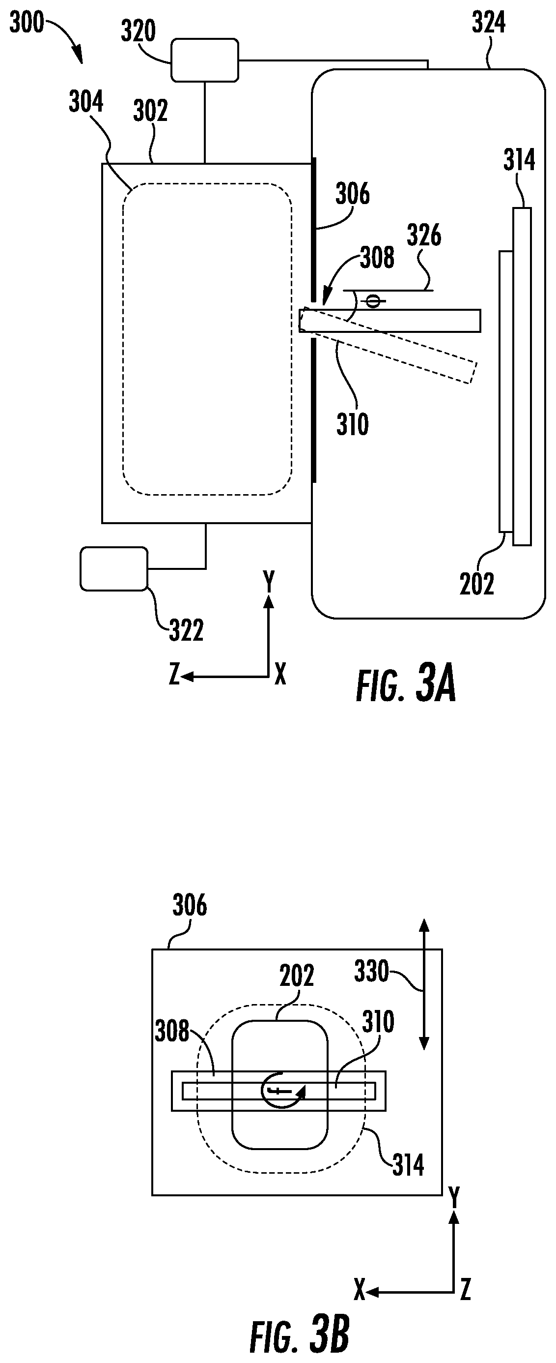
[0020]Methods in accordance with the present disclosure will now be described more fully hereinafter with reference to the accompanying drawings, where embodiments of the methods are shown. The methods may be embodied in many different forms and are not to be construed as being limited to the embodiments set forth herein. Instead, these embodiments are provided so the disclosure will be thorough and complete, and will fully convey the scope of the system and method to those skilled in the art.

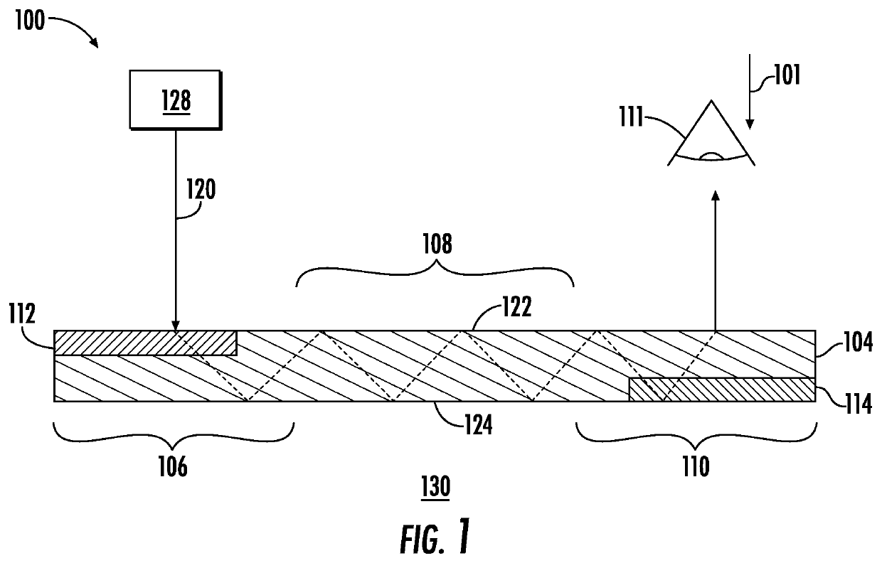
[0021]FIG. 1 is a schematic, cross-sectional view of a waveguide 104 implemented in a display apparatus 100. The display apparatus 100 may be configured for augmented, virtual, and mixed or merged reality applications as well as other display applications, for example, hand held display devices.

[0022]The display apparatus 100 uses the waveguide 104 for transparent viewing of an ambient environment 130 through the waveguide 104, such as for a user viewing the environment 130 from a user perspect...


PUM


Abstract

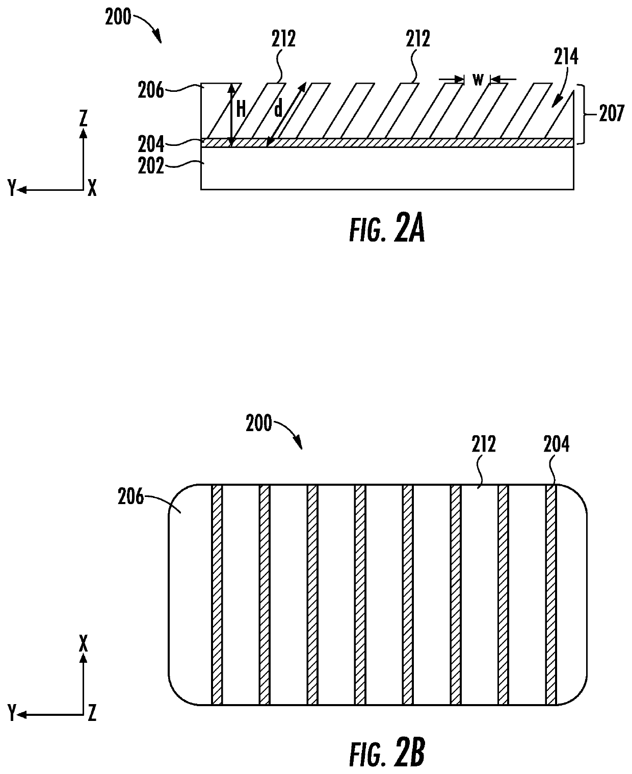
Methods of producing gratings with trenches having variable height are provided. In one example, a method of forming a diffracted optical element may include providing an optical grating layer over a substrate, patterning a hardmask over the optical grating layer, and forming a sacrificial layer over the hardmask, the sacrificial layer having a non-uniform height measured from a top surface of the optical grating layer. The method may further include etching a plurality of angled trenches into the optical grating layer to form an optical grating, wherein a first depth of a first trench of the plurality of trenches is different than a second depth of a second trench of the plurality of trenches.

Description

FIELD OF THE DISCLOSURE[0001]Embodiments of the present disclosure generally relate to methods of producing optical gratings. More specifically, the disclosure relates to methods of producing slanted optical gratings with trenches having variable depths.BACKGROUND OF THE DISCLOSURE[0002]Optical elements such as optical lenses have long been used to manipulate light for various advantages. Recently, micro-diffraction gratings have been utilized in holographic and augmented / virtual reality (AR and VR) devices. One particular AR and VR device is a wearable display system, such as a headset, arranged to display an image within a short distance from a human eye. Such wearable headsets are sometimes referred to as head mounted displays, and are provided with a frame displaying an image within a few centimeters of the user's eyes. The image can be a computer-generated image on a display, such as a micro display. The optical components are arranged to transport light of the desired image, w...

Claims


Application Information

Patent Timeline
IPC IPC(8): G02B5/18B29D11/00G02B6/02
CPCG02B5/1828B29D11/00769G02B6/02138G02B5/1857G02B6/00G02B6/0026
Inventor EVANS, MORGANMEYER TIMMERMAN THIJSSEN, RUTGEROLSON, JOSEPH C.
Owner APPLIED MATERIALS INC
Learn More