Supercharge Your Innovation With Domain-Expert AI Agents!

Semiconductor device, inverter, and automobile

a technology of inverter and semiconductor, applied in the direction of electric motor control, electronic switching, pulse technique, etc., can solve the problem of excessive through-current to flow into, and achieve the effect of reliably preventing an arm shor

Active Publication Date: 2020-11-10
MITSUBISHI ELECTRIC CORP
View PDF13 Cites 1 Cited by
  • Summary
  • Abstract
  • Description
  • Claims
  • Application Information

AI Technical Summary

Benefits of technology

The present invention provides a semiconductor device with a circuit that prevents arm shorts through a process called dead-time generation. This results in a reliable semiconductor device.

Problems solved by technology

In driving control of a switching device connected between a high potential power supply terminal and a low potential power supply terminal to form a totem-pole connection and operate complementarily, it is conventionally required to prevent a problem in that a high-potential-side switching device connected to the high potential power supply terminal and a low-potential-side switching device connected to the low potential power supply terminal are turned on at the same time to cause a short circuit between the high potential power supply terminal and the low potential power supply terminal, thereby causing an excessively large through-current to flow into the high-potential-side switching device and the low-potential-side switching device.

Method used


Image

  • Semiconductor device, inverter, and automobile
  • Semiconductor device, inverter, and automobile
  • Semiconductor device, inverter, and automobile

Examples


first embodiment

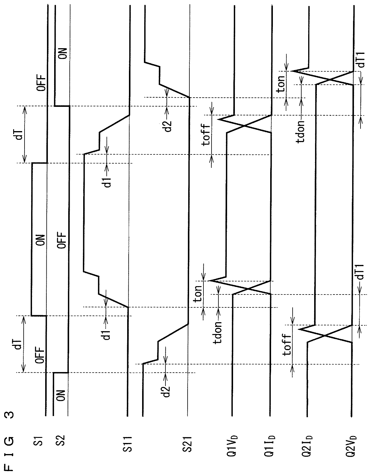
[0084]According to the prior art, when a resistance value of each of the gate resistors R1 and R2 is changed by the soft shut-off function of the protection circuit to change the turn-on and turn-off times of the corresponding one of the transistors Q1 and Q2, a dead time to be added to each of the gate on-off command signals S1 and S2 needs to be adjusted each time. In contrast, the half-bridge circuit 100 of the first embodiment allows the actual dead time PdT to extend or shorten in accordance with the increase and decrease of the turn-on and turn-off times of each of the transistors Q1 and Q2, so that a dead time to be added to each of the gate on-off command signals S1 and S2 does not need to be adjusted.

[0085]This is because there are provided the upper status-detection circuit STH and the lower status-detection circuit STL to determine whether the corresponding transistors Q1 and Q2 are in turn-off operation on the basis of gate voltages of the respective transistors Q1 and Q...

fourth embodiment

[0118]FIG. 9 is a conceptual diagram illustrating a configuration of a vehicle 400 in which a motor is controlled using the three-phase inverter 300 incorporating a dead-time generation circuit.

[0119]An electric vehicle such as a hybrid vehicle, a plug-in hybrid vehicle, an electric vehicle, a fuel cell vehicle, or the like, as well as an automobile driven by an internal combustion engine, provided with a regenerative motor such as a starter-generator, includes a running motor and an electric-power regenerative motor. FIG. 9 illustrates a configuration using the three-phase inverter 300 incorporating a dead-time generation circuit for driving control of a three-phase motor MT of each of them.

[0120]While a hybrid vehicle, a plug-in hybrid vehicle, an electric vehicle, a fuel cell vehicle, and an automobile provided with a starter-generator or the like, each include a motor with an output of 1 kW or more, the motor has a large load fluctuation and alternately repeats power running an...


PUM


Abstract

The present invention relates to a semiconductor device provided with a dead-time generation circuit, the semiconductor device including: first and second status-detection circuits that each have a function of detecting whether first and second switching devices are in turn-off operation to output first and second status signals, respectively, and each have a function of generating a dead time of on-off operation of the corresponding one of the first and second switching devices; a first logic circuit that receives a first on-off command signal instructing the first switching device to be turned on or off, and the second status signal to output a signal allowing the first switching device to be turned on only when the second switching device is not in turn-off operation; and a second logic circuit that receives the first on-off command signal instructing the second switching device to be turned on or off, and the first status signal to output a signal allowing the second switching device to be turned on only when the first switching device is not in turn-off operation.

Description

TECHNICAL FIELD[0001]The present invention relates to a semiconductor device including a dead-time generation circuit connected in series to generate a dead time in driving of a switching device that operates complementarily.BACKGROUND ART[0002]In driving control of a switching device connected between a high potential power supply terminal and a low potential power supply terminal to form a totem-pole connection and operate complementarily, it is conventionally required to prevent a problem in that a high-potential-side switching device connected to the high potential power supply terminal and a low-potential-side switching device connected to the low potential power supply terminal are turned on at the same time to cause a short circuit between the high potential power supply terminal and the low potential power supply terminal, thereby causing an excessively large through-current to flow into the high-potential-side switching device and the low-potential-side switching device.[00...

Claims


Application Information

Patent Timeline
Patent Type & Authority Patents(United States)
IPC IPC(8): H02M7/5387H02P27/08H02P29/024H03K17/0812
CPCH02P29/0241H02M7/53871H02P29/024H02P27/08H03K17/08122H02P29/027H02M1/38H03K17/162H03K17/163
Inventor HIYAMA, KAZUAKI
Owner MITSUBISHI ELECTRIC CORP
Features
  • R&D
  • Intellectual Property
  • Life Sciences
  • Materials
  • Tech Scout
  • Unparalleled Data Quality
  • Higher Quality Content
  • 60% Fewer Hallucinations
Learn More