
Reducing interference from channel holders in an optical link

a channel holder and optical link technology, applied in the field of optical communication networks, can solve the problems of introducing significant non-linear noise, interference in the optical signal may affect the specific, and affecting the specific, and achieve the effect of reducing interferen

Active Publication Date: 2020-11-10
CIENA
View PDF26 Cites 5 Cited by
  • Summary
  • Abstract
  • Description
  • Claims
  • Application Information

AI Technical Summary

Benefits of technology

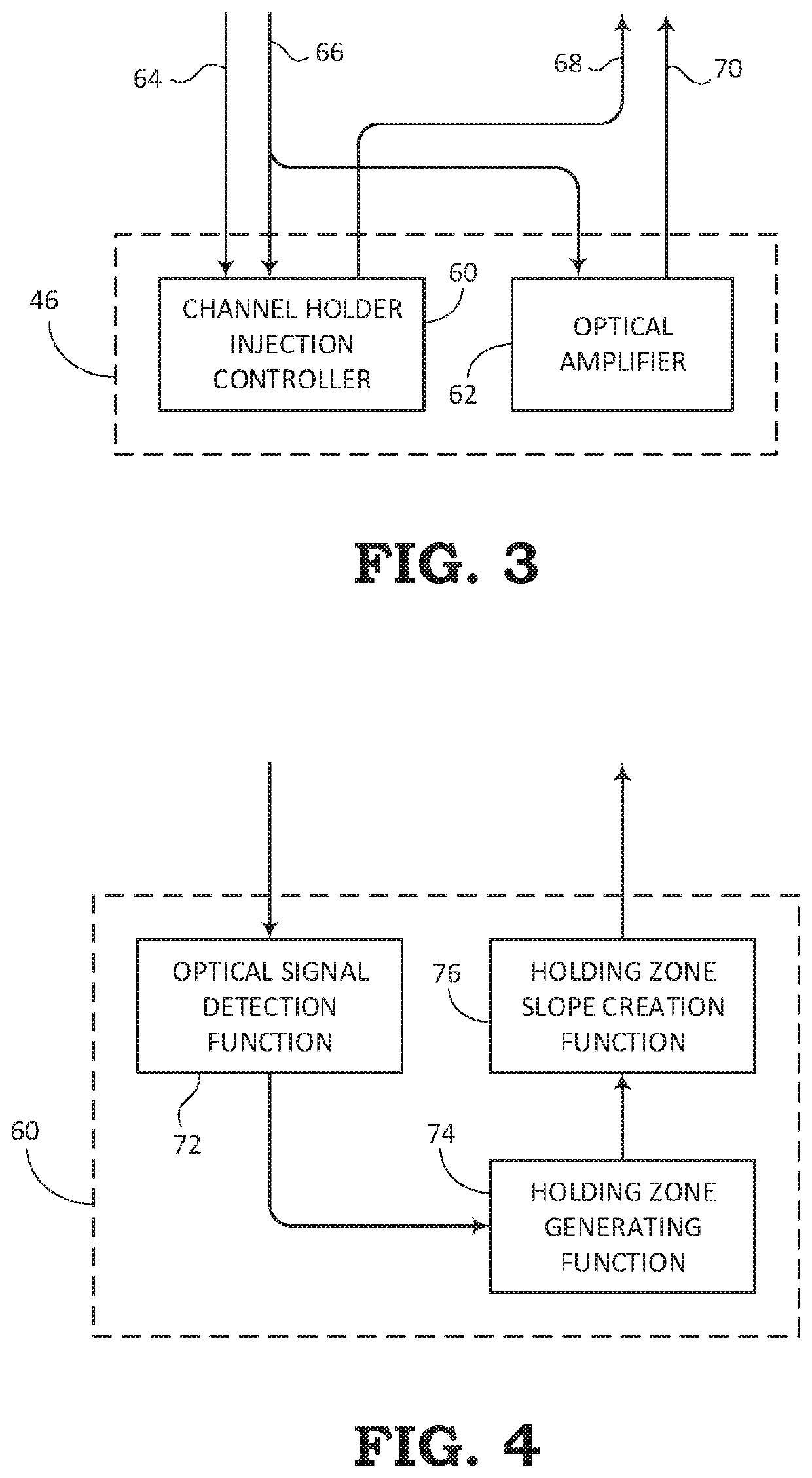
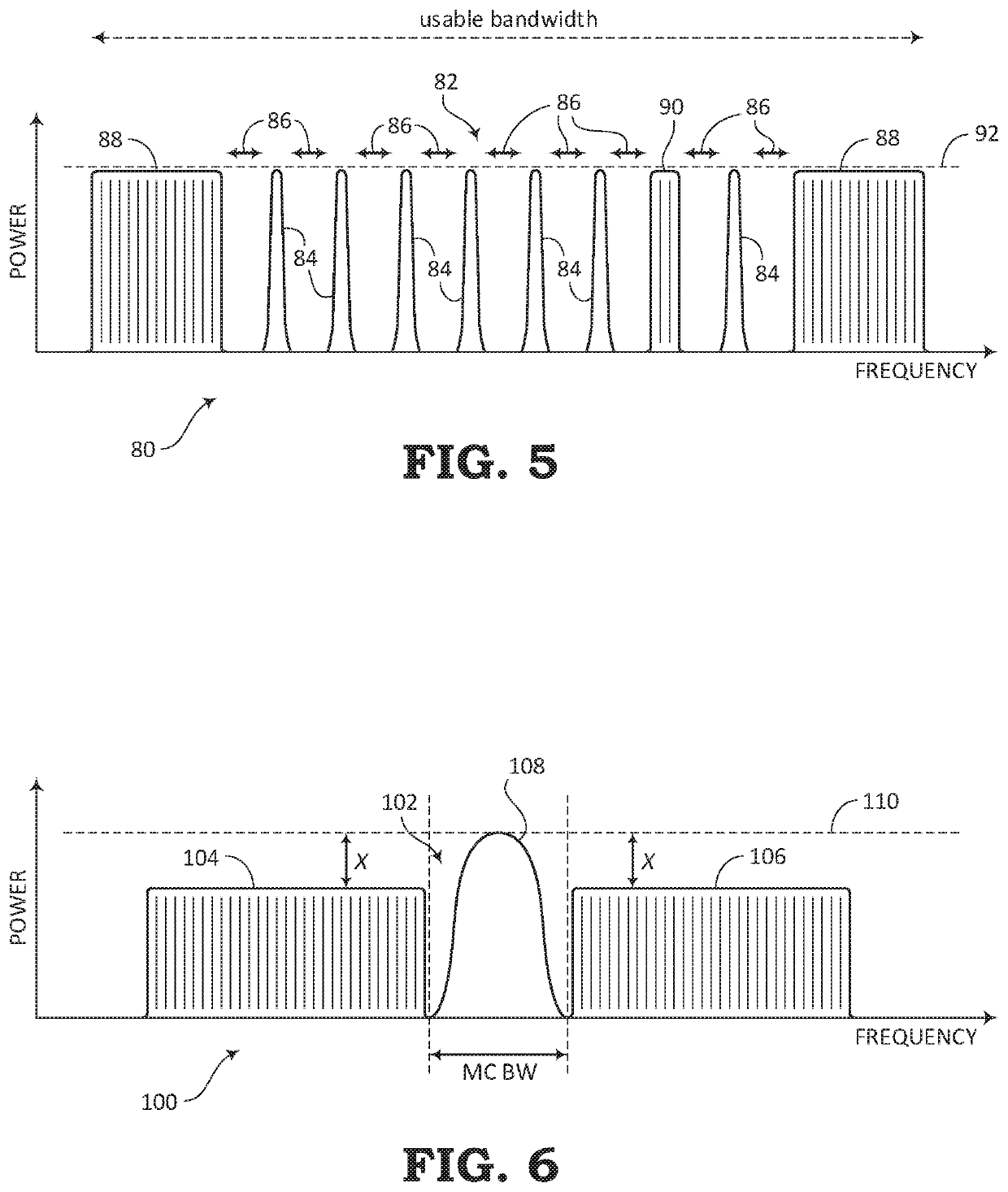
The patent describes methods and systems for reducing interference in optical networks caused by the introduction of channel holders. Channel holders are used to create a lower frequency holding zone and a higher frequency holding zone around an added optical channel to prevent interference. The shape of the power spectral density of the channel holders is dynamically configured based on link budget requirements and signal-to-noise ratios. The technical effects of the patent include reducing interference, improving signal quality, and optimizing network performance. Additionally, the patent describes an optical add / drop multiplexer (OADM) that performs various functions, including adding an optical channel, creating holding zones, and dynamically adjusting the power spectral density of the channel holders.

Problems solved by technology

However, traditional ASE-based channel holders can provide a significant amount of interference for certain types of optical signals and certain types of fibers.
For example, interference in the optical signals may affect the specific transmission modes (e.g., Baud rate, line rate, modulation format, etc.) in certain fiber types.
The interference of the channel holders may not be an issue for all fiber types, but may introduce significant non-linear noise for certain fiber types, such as True Wave Reduced Slope (TWRS), True Wave Classic (TWC), Non-Zero Dispersion-Shifted Fiber (NZDSF), etc.

Method used


Image

  • Reducing interference from channel holders in an optical link
  • Reducing interference from channel holders in an optical link
  • Reducing interference from channel holders in an optical link

Examples


Embodiment Construction

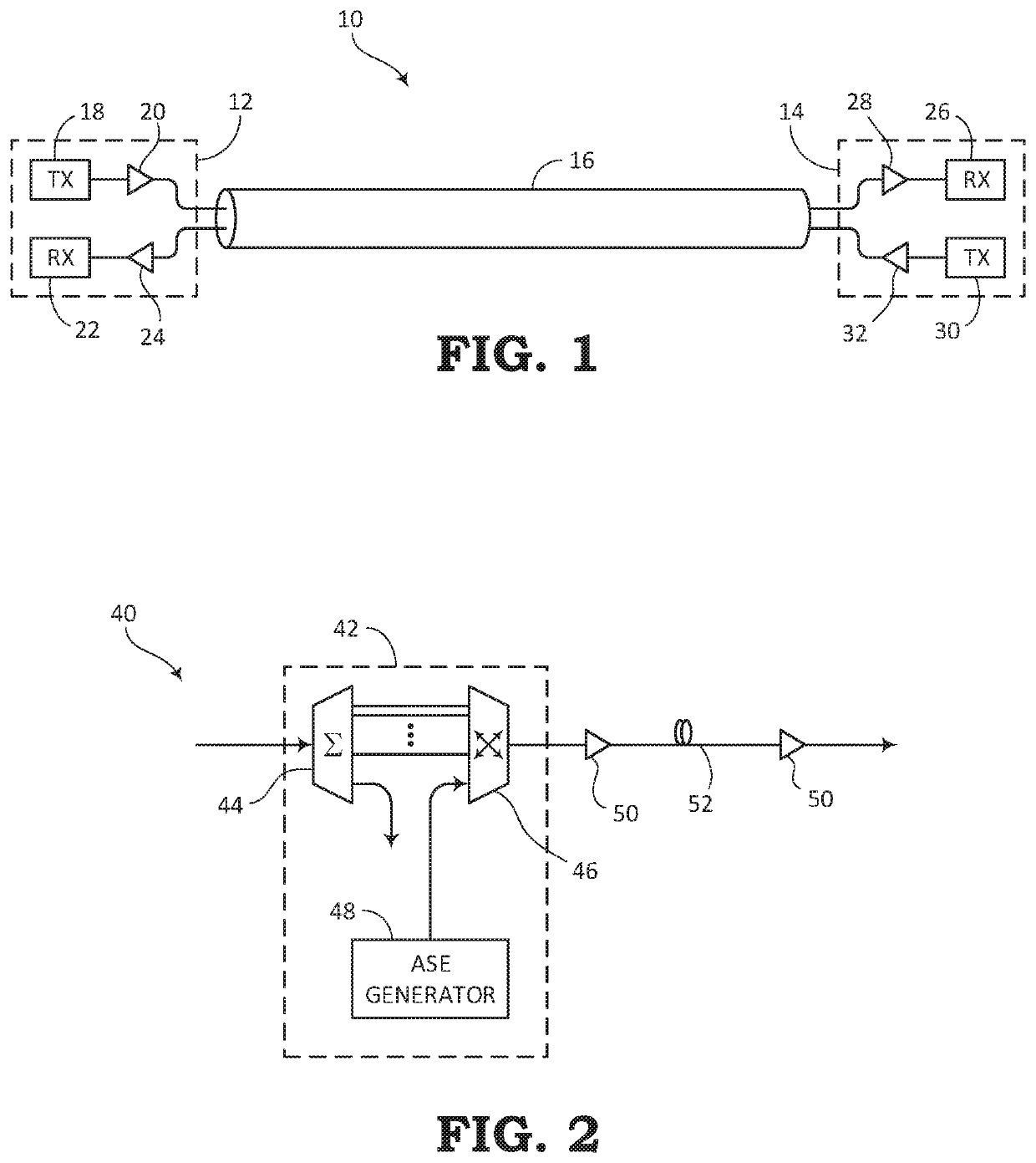
[0026]The present disclosure relates to systems and methods for communicating optical signals within an optical communication system. The optical signals can be amplified through the optical communication system by a process referred to as Amplified Spontaneous Emission (ASE). In addition to amplifying the data portion of the optical signals, the ASE process may also include filling unused bandwidth with channel holders for maintaining a certain power level throughout the usable spectrum. The present disclosure describes an improvement over conventional ASE channel holding techniques by substantially maintaining the target total launch power, while further providing the benefit of reducing the interference that the channel holders may normally cause to the useful optical data signals.

[0027]The systems and methods described in the present disclosure may be used in a Reconfigurable Line System (RLS). The channel holder creation and injection systems for adding channel holders based on...


PUM


Abstract

Systems and methods are provided for reducing interference when optical signals are added. One embodiment includes a method for adding an optical channel for communicating data and having a bandwidth within an optical spectrum for transmission along an optical link of an optical network. The method includes creating a lower frequency holding zone having a lower frequency bandwidth adjacent to the bandwidth of the added optical channel and including at least one lower frequency sub-slice having a power spectral density that varies throughout the lower frequency sub-slice. Also, the method includes creating a higher frequency holding zone having a higher frequency bandwidth adjacent to the bandwidth of the added optical channel and including at least one higher frequency sub-slice having a power spectral density that varies throughout the higher frequency sub-slice. The lower frequency holding zone and the higher frequency holding zone are dynamically configured with respect to fiber and channel requirements.

Description

TECHNICAL FIELD[0001]The present disclosure generally relates to optical communication networks. More particularly, the present disclosure relates to optical links within an optical network and systems and methods for reducing interference in an optical link caused by the addition of channel holders for filling the optical spectrum.BACKGROUND[0002]In an optical communication system or network, optical signals having specific spectral characteristics are generally transmitted from one end of an optical transmission line (e.g., fiber optic cable) to a receiving end, where the optical signals can be decoded. Normally, the optical signals include a predetermined frequency band or spectrum, which may contain at least modulated data along with other signals. For example, empty bandwidth slots are typically filled with channel holders that are designed to equalize the power along the entire spectrum. Channel holders are also configured to reduce noise.[0003]Optical networks usually include...

Claims


Application Information

Patent Timeline
Patent Type & Authority Patents(United States)
IPC IPC(8): H04J14/02H04B10/564G02B6/293
CPCH04J14/021G02B6/29383H04B10/564H04J14/0221H04J14/0206H04J14/0213H04J14/0208H04J14/0201H04J14/022H04J14/0215H04J14/0202H04J14/0224H04J14/0212
Inventor AL SAYEED, CHOUDHURY A.
Owner CIENA
Learn More