Method and long-stator linear motor for transferring a transport unit at a transfer position

a technology of longstator and transport unit, which is applied in the direction of transportation and packaging, propulsion systems, and association with control/drive circuits. it can solve the problems of increasing the effort needed to implement a transport device, inability to individually transport individual transport units, and inability to transfer individual transport units

Active Publication Date: 2020-11-24
B&R IND AUTOMATION GMBH
View PDF24 Cites 0 Cited by
  • Summary
  • Abstract
  • Description
  • Claims
  • Application Information

AI Technical Summary

Benefits of technology

[0012]Embodiments are directed to a transport device in the form of a long-stator linear motor in which the available electrical power of the power unit of the long-stator linear motor can be better utilized to generate a stator current of a drive coil in a transfer position for steering a transport unit.
[0013]Aspects of the embodiments are achieved by impressing a stator current into the drive coils interacting with the transport unit on a first side of the transport unit in the transfer area in order to generate the steering effect on this first side, which stator current either generates only an electromagnetic lateral force or causes only a braking force against the movement direction of the transport unit, or only a combination thereof. This way, in order to generate the steering effect on the transport unit on this first side, no electrical energy for generating an electromagnetic propulsive force has to be provided. The entire available power of the power unit of the long-stator linear motor for energizing the drive coils on this first side can thereby flow into the generation of the steering effect. This way, the steering effect itself can also be increased, because all electrical energy can flow into the generation of the steering effect and a safer steering of the transport unit can be achieved.

Problems solved by technology

With such conventional continuous conveyors, flexibility is considerably limited, in particular individual transport of individual transport units is not possible.
However, the additional auxiliary coils required increase the effort needed to implement a transport device, as the auxiliary coils have to be additionally installed and electrically supplied and actuated.
But that brings with it certain problems.
This could lead to congestion of the transport units in the turnout area, which would be unfavorable for controlling the transport device.
If the lateral force is overdimensioned for safety reasons during turnout travel, this leads to increased friction and increased wear.
The transport units would thereby have to be mechanically dimensioned accordingly, making the transport units larger, heavier and more expensive.
In addition, this also increases wear on the mechanical components of the transport units, in particular the mechanical guide members.
Therefore, reversing the polarity to trigger the turnout for the operation of a long-stator linear motor is also rather disadvantageous.
The power unit of the long-stator linear motor which supplies the drive coils with current is, however, limited in terms of power and can therefore only provide a certain maximum current.
Therefore, the available current, at least in the transfer area, cannot be fully used to generate the propulsive force.
Since usually no steps in the propulsion force are desired (which can lead to steps in acceleration or jerk), this also limits the current available for the propulsion force outside the transfer area.
However, since a long-stator linear motor contains a large number of drive coils (a number in the order of hundreds or thousands is not uncommon), such a hardware change would significantly increase the total costs of the long-stator linear motor.

Method used


Image

  • Method and long-stator linear motor for transferring a transport unit at a transfer position
  • Method and long-stator linear motor for transferring a transport unit at a transfer position
  • Method and long-stator linear motor for transferring a transport unit at a transfer position

Examples


first embodiment

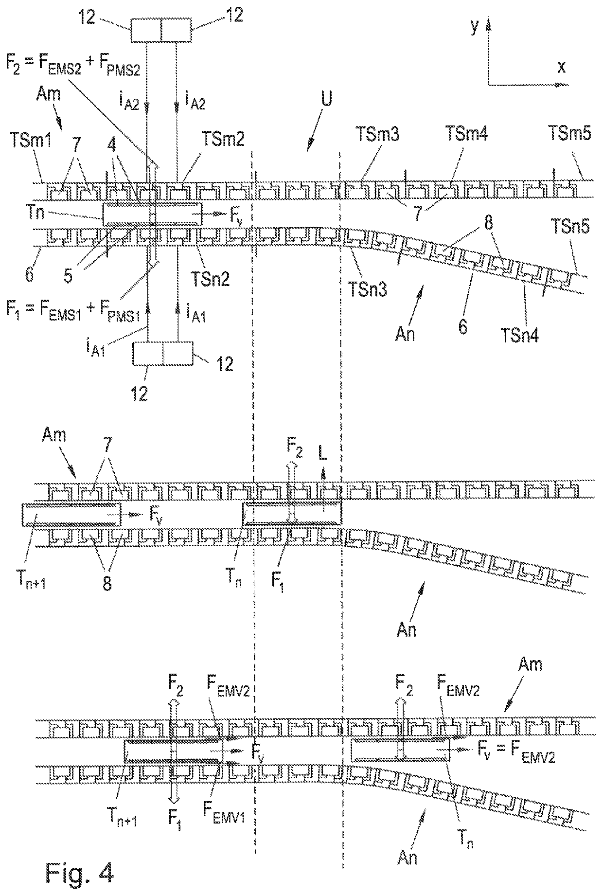
[0019]FIG. 4 shows a method according to the invention for transferring a transport unit at a transfer position; and

second embodiment

[0020]FIG. 5 shows a method according to the invention for transferring a transport unit at a transfer position.

DETAILED DESCRIPTION OF THE EMBODIMENTS

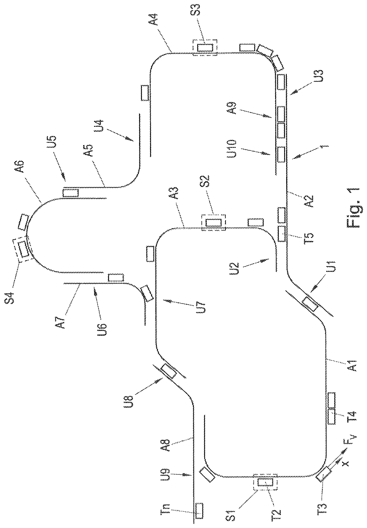
[0021]FIG. 1 shows an example of a transport device 1 in the form of a long-stator linear motor. The transport device 1 consists of a number of transport sections A1 . . . A9, which are combined to form a transport device 1. This modular structure enables a very flexible design of the transport device 1, but also requires a plurality of transfer positions U1 . . . U9, at which the transport units T1 . . . Tn moved on the transport device 1 are transferred from one transport sections A1 . . . A9 to another (for reasons of clarity, not all transport units are marked with a reference sign in FIG. 1). n is an index that stands for the existing number of transport units.

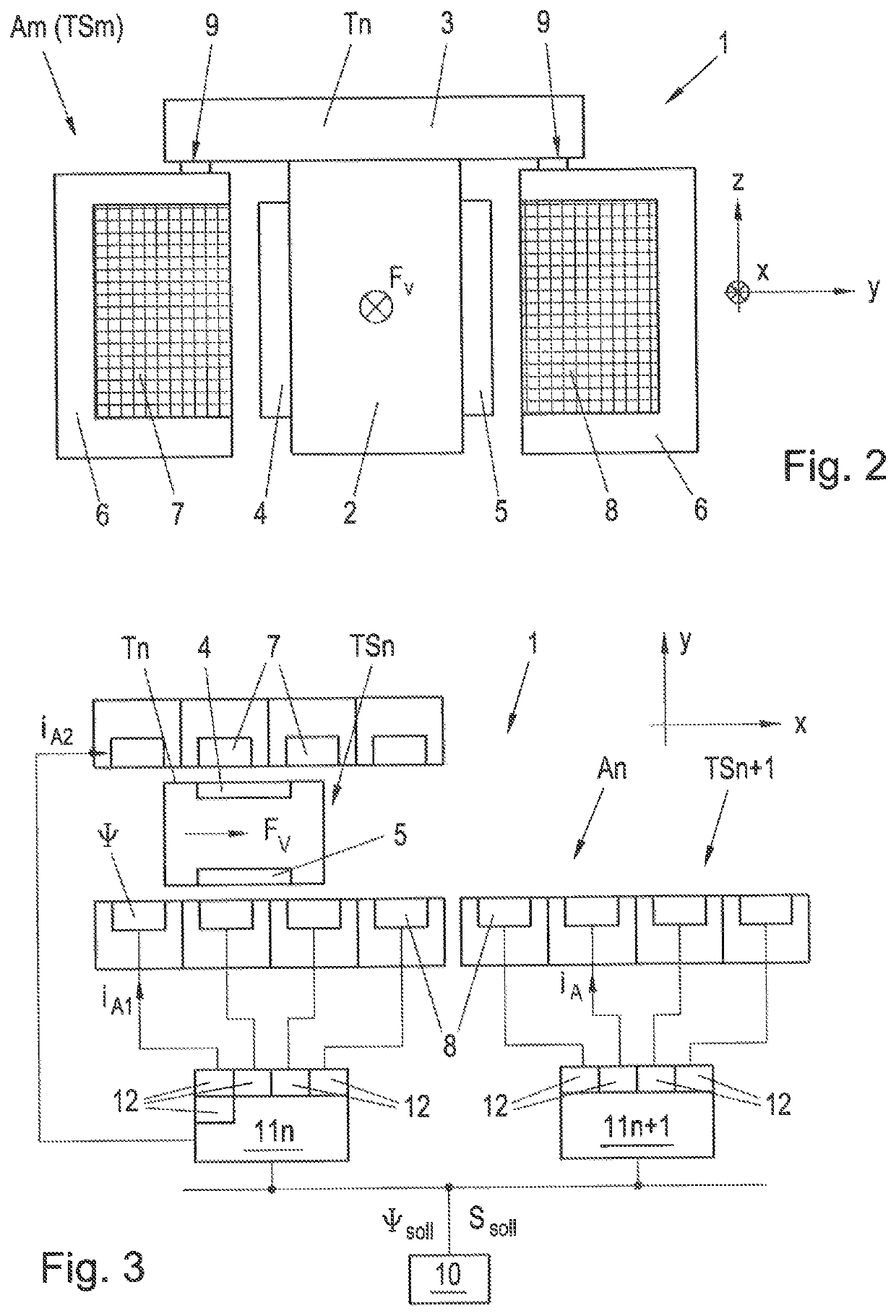
[0022]The transport device 1 is designed as a long-stator linear motor in which the transport sections A1 . . . A9 each form a part of a long-stator of a long-stator linear...


PUM


Abstract

In order to implement a transfer position in a long-stator linear motor, in which position a transport unit is magnetically steered in order to be deflected from a first transport sections to a second transport section, a stator current is impressed into the drive coils interacting with the transport unit on a first side of the transport unit in the transfer area in order to generate the steering effect on this first side, which stator current either generates only an electromagnetic lateral force or causes only a braking force against the movement direction of the transport unit, or only a combination thereof.

Description

CROSS-REFERENCE TO RELATED APPLICATIONS[0001]The present application claims priority under 35 U.S.C. § 119(a) of European Patent Application No. 18176080.2 filed Jun. 5, 2018, the disclosure of which is expressly incorporated by reference herein in its entirety.BACKGROUND OF THE INVENTION1. Field of the Invention[0002]The present invention relates to a method of transferring a transport unit of a long-stator linear motor at a transfer position from a first transport section, having a number of drive coils arranged one behind the other in the movement direction of the transport unit in the area of the transfer position, to a second transport section, having a number of drive coils arranged one behind the other in the movement direction of the transport unit in the area of the transfer position, wherein excitation magnets being arranged on each side of the transport unit, which excitation magnets, in order to move the transport unit in the movement direction, interact with drive coils...

Claims


Application Information

Patent Timeline
Patent Type & Authority Patents(United States)
IPC IPC(8): H02K41/02H02K41/03H02K11/30B65G54/02
CPCH02K11/30B65G54/02H02K41/03B65G2201/02B60L13/003B60L13/03B60L15/005B60L15/2036Y02T10/72H02P25/064H02K41/031B65G2812/99
Inventor WEBER, ANDREASFORTHUBER, FRIEDRICH
Owner B&R IND AUTOMATION GMBH
Why Eureka
Try Eureka