Sacroiliac joint stabilization and fixation devices and related methods

a sacroiliac joint and fixation device technology, applied in the field of joint fixation devices, can solve the problems of relying on screw thread fixation and/or a simple compression fit in the soft cancellous bone, and traditional open surgical techniques for sacroiliac joint fusion carry a significant risk of complications, so as to promote sacroiliac joint fusion and support the patient's body weight, the effect of resisting rotational and translational forces

Active Publication Date: 2020-12-15
WEST END BAY PARTNERS LLC
View PDF56 Cites 6 Cited by
  • Summary
  • Abstract
  • Description
  • Claims
  • Application Information

AI Technical Summary

Benefits of technology

[0006]The embodiments described herein include the benefits of provide strong constructs that can sustain the weight of the patient's body, resist rotational and translational forces across the SI joint, promote sacroiliac joint fusion over time, and / or take advantage of the sacral cortical layer to resist pull-out. Furthermore, the embodiments described herein include the benefit of a reduced overall outer diameter of the device and a reduced overall length such that multiple devices may be placed closer together and such that the incision needed to insert the device is minimized.
[0020]Some embodiments include inserting a second guidewire across the SI joint such that the guidewire extends through the ilium and at least partially into the sacrum; positioning a second anchor device over the second guidewire, where the second anchor device includes: a second housing, wherein the second housing comprises: an inner anchor; an outer anchor; and one or more apertures; one or more engagement members at least partially disposed in the second housing, where at least one of the one or more engagement members is movable between a retracted position and an extended position such that, when the at least one of the one or more engagement members is in the extended position, the at least one of the one or more engagement members extends through at least one of the one or more apertures; wherein the second anchor device comprises a continuous channel extending from a first end of the anchor second device to a second end of the anchor second device, the channel being configured to receive the second guidewire; moving the second anchor device across the SI joint such that the second anchor device extends through the ilium and at least partially into the sacrum; moving a second actuating screw in the channel of the second housing toward the second end of the second anchor device, thereby causing longitudinal movement of the at least one of the one or more engagement members; rotating the at least one of the one or more engagement members of the second anchor device from the retracted position to the extended position, wherein the at least one of the one or more engagement members move to the extended position within cancellous bone of the sacrum; urging, when the at least one of the one or more engagement members of the second anchor device is in the extended position, the inner anchor of the second anchor device towards the outer anchor of the second anchor device to reduce a width of the SI joint; and urging, when the at least one of the one or more engagement members of the anchor device is in the extended position, the inner anchor of the anchor device towards the outer anchor of the anchor device to reduce a width of the SI joint.

Problems solved by technology

Traditional open surgical techniques for sacroiliac joint fusion carry a significant risk for complications.
A disadvantage, however, of these devices is the reliance on screw thread fixation and / or a simple compression fit in the soft cancellous bone of the sacrum.

Method used


Image

  • Sacroiliac joint stabilization and fixation devices and related methods
  • Sacroiliac joint stabilization and fixation devices and related methods
  • Sacroiliac joint stabilization and fixation devices and related methods

Examples


Embodiment Construction

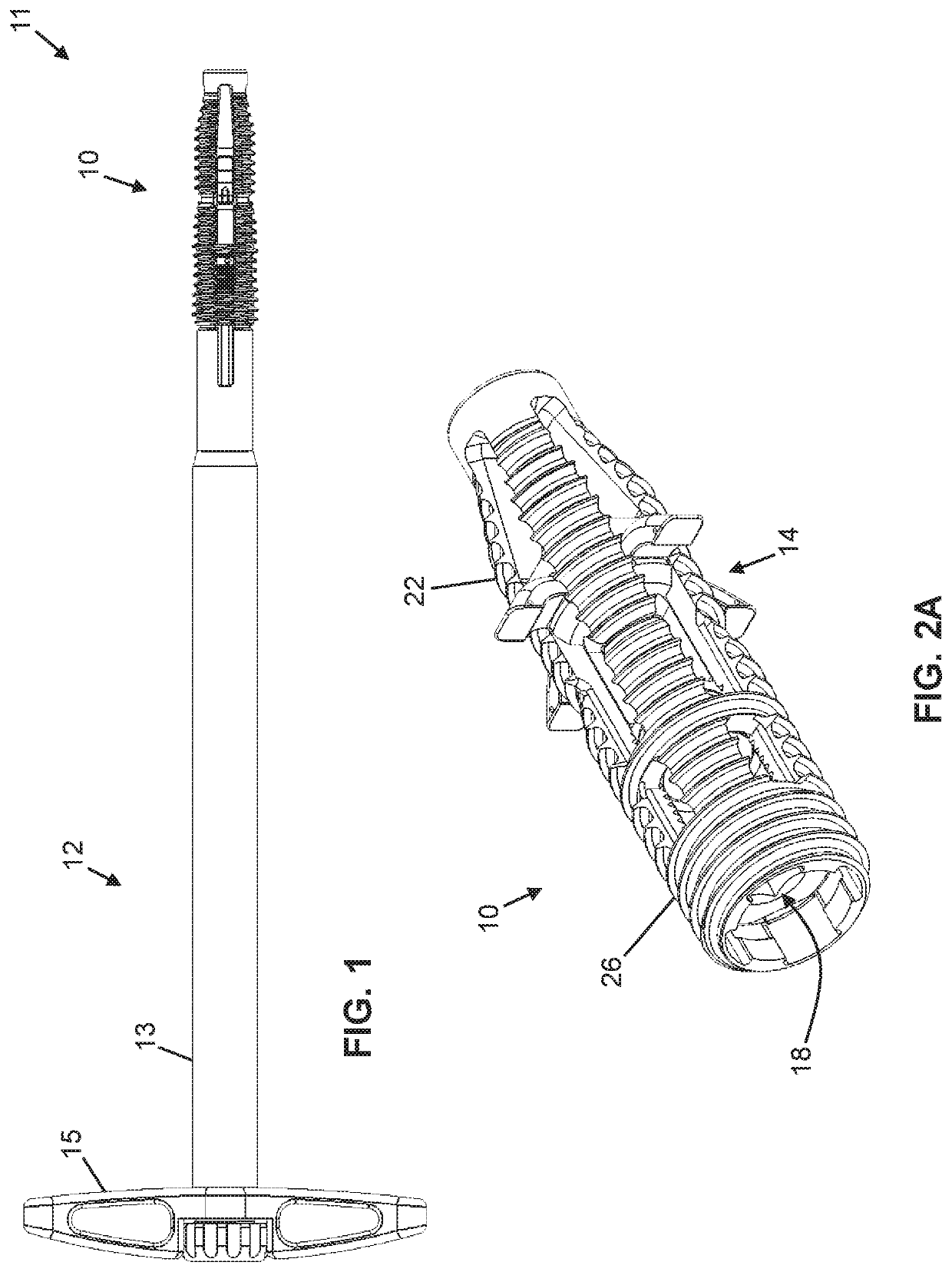
[0036]Referring now to the drawings, and more particularly to FIGS. 1-2E, shown therein and designated by the reference numeral 10 is one embodiment of the present anchor devices. Device 10 can be a component in an anchor assembly 11 that includes a driver tool 12 having a cannula 13 coupled to a handle 15. Device 10 may be removably coupled to cannula 13 such that, when the device is appropriately positioned across a sacroiliac joint (“SI joint”) (e.g., 62) (FIGS. 16A and 16B), the cannula can be detached from the device.

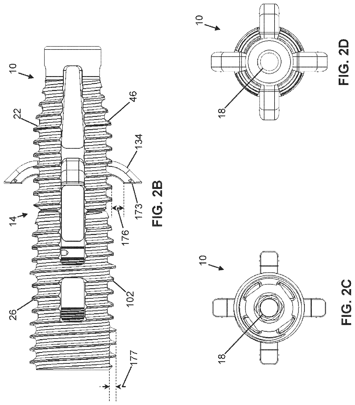
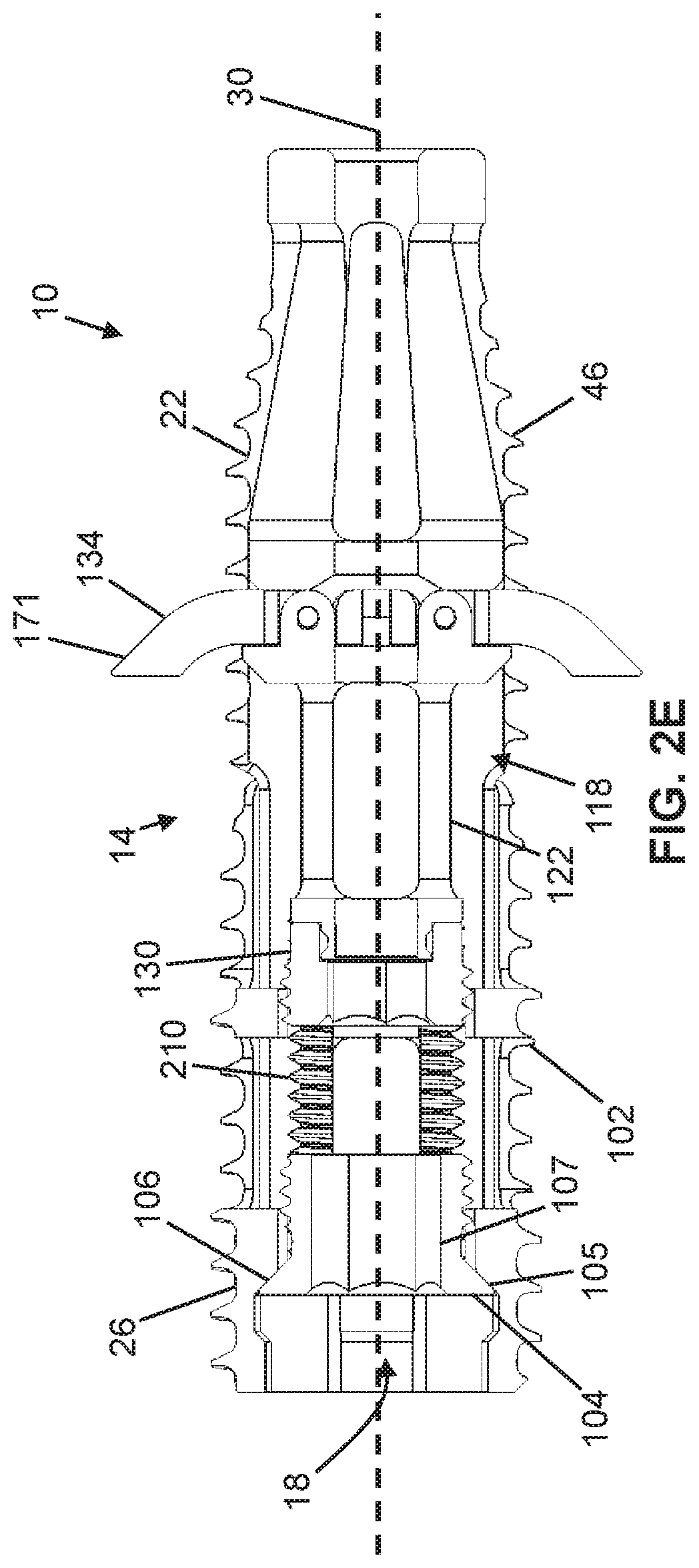
[0037]In the embodiment shown, device 10 includes an elongated housing 14 having a channel 18 extending therethrough. In the depicted embodiment, housing 14 comprises an inner anchor 22 movable (e.g., axially) relative to an outer anchor 26. In this embodiment, components of device 10 may be characterized by and described relative to a longitudinal axis 30 extending along a length thereof.

[0038]Referring specifically to FIGS. 4A-4D, inner anchor 22 includes a first...


PUM


Abstract

An anchor device for use in sacroiliac joint stabilization comprises a housing having one or more apertures; one or more engagement members at least partially disposed in the housing, where at least one of the one or more engagement members is movable between a retracted position and an extended position such that, when in the extended position, the at least one of the one or more engagement members extends through at least one of the one or more apertures; wherein, when in the extended position, the at least one of the one or more engagement members is configured to move to the extended position within cancellous bone of a sacrum; and wherein the anchor device comprises a continuous channel extending from a first end of the anchor device to a second end of the anchor device, the channel being configured to receive a guidewire.

Description

CROSS-REFERENCE TO RELATED APPLICATIONS[0001]The application claims priority to U.S. Provisional Application No. 62,622,649, filed Jan. 26, 2018, the entire contents of which is specifically incorporated by reference herein without disclaimer.BACKGROUND OF THE INVENTION1. Field of the Invention[0002]The present invention relates generally to joint fixation devices, and more particularly, but not by way of limitation, to sacroiliac joint fixation devices and related methods.2. Description of Related Art[0003]The sacroiliac joint is a strong, weight-bearing synovial joint and part of the pelvis. The joint is comprised of strong ligamentous attachments and two articular dense cortical surfaces: the sacrum and the ileum. The body of both the sacrum and the ileum consists of soft cancellous bone.[0004]The sacroiliac joint has been identified as a source of pain and disability in a large number of patients. Pain of the sacroiliac joint may be a result of bone degeneration, fracture, dislo...

Claims


Application Information

Patent Timeline
Patent Type & Authority Patents(United States)
IPC IPC(8): A61B17/70A61B17/84A61B17/86A61B17/88
CPCA61B17/8625A61B17/7055A61B17/8685A61B17/844A61B17/8888A61B2017/8655A61B2017/681A61B17/7082
Inventor REDMOND, ANDY J.GORDON, CHARLES R.WAGNER, ERIKLANDRY, MICHAEL E.
Owner WEST END BAY PARTNERS LLC
Why Eureka
Try Eureka