Wind wheel with blade elbow bend

a technology of wind turbines and elbows, which is applied in the direction of wind turbines, engine components, wind energy generation, etc., can solve the problems of limiting the use of the long wing-shaped blade lever action to increase complicating technological problems, and certain technical difficulties, so as to reduce the possibility of breakage, improve the rotational effect in other parameters, and complicate technological problems.

Active Publication Date: 2020-12-15
SHAIKENOV BLOK +1
View PDF21 Cites 0 Cited by
  • Summary
  • Abstract
  • Description
  • Claims
  • Application Information

AI Technical Summary

Benefits of technology

[0005]The disadvantage of the invention is that the short part is made of cast lithium, which complicates the technological problems of working the metal at the connection of the axial end with the hub and with the internal structure of the sleeve segment for connection with the handle of the wing-shaped part of the blade. The compatibility of the fiberglass sheathing with the steel axial short part, which have different degrees of expansion and compression under various temperature conditions (high and low temperatures), creates a certain technical difficulty.
[0006]The prior art disclosed in KZ 29206 F03D includes blades consisting of two parts: a short root part and a long wing-shaped part. The short root part consists of an axial segment connected to the hub of the wind plant and a sleeve segment to which the handle of the wing-shaped part of the blade is connected. The two segments are made separately of strong steel. The axial and sleeve segments are connected at a 30-45° angle to form an elbow bend. The angular bend is oriented backward, against the rotation of the wind wheel. Steel cables between the axial and sleeve segments are drawn to prevent breakage on the elbow bend.
[0007]The disadvantages of this invention are the narrow parameters of the angular connection of the axial and sleeve segments (30-45°) forming the elbow bend of the short root part of the blade, which limits the possible use of the lever action of the long wing-shaped blade to increase the rotational effect in other parameters. The technical concept and reliability of the hinge mechanisms of the connection of the sleeve segment skeleton with the connecting shaft of the wing-shaped blade, where the support rings of the sleeve segment and the annular protuberances of the wing-shaped blade are single, raise certain doubts. Their functionality is not clearly stated, since the end flange facing the wing-shaped blade and the locking disk on the elbow bend bear the main load on the attachment of these mechanisms.
[0008]The prior art disclosed FR 2863318A1 includes a blade handle that has a bend against the direction of the wind, and the long part of the blade assumes an angular position relative to the axis of the handle passing along the straight part, which was conceived to reduce aerodynamic perturbations created by the passage of the aforementioned blades before the tower mast. One part of the bend represents the continuation of the axial line and is partly sunken to the hub. The second part of the bend, which makes up an angle with the first part, is situated on a straight line with long wing-shaped blade, as shown in FIGS. 8, 9, and 10 (FR 2863318A1) passing from its tip to the connection with the hub. The blade handle is one piece, so the action of the lever or blade is transmitted through one support, the blade's connection to the plant hub, so distortions of the handle contribute little more to amplifying the blade rotation and correspondingly to the capacity of the wind plant.
[0009]The prior art disclosed in WO 2008 / 064678 A2 includes a wind power plant blade with an attaching device for mounting in a circular pitch bearing, such that the blade's axis is disposed at an angle relative to the blade's longitudinal axis, which permits elliptical intersection of the main axis, and the distance between the outer part of the blade and the support is increased, while the front edge of the blade rises upward toward the wind.
[0010]According to the description, this is achieved by the fact that the blades consist of two parts: a short base that is secured to the hub of the plant, perpendicularly to the horizontal axis of the main shaft, and a long blade mounted on the pitch plane (Yuryev-Sikorsky device) of the short part, which can then also perform rotation along its longitudinal axis. The main purpose of this two-part device is to ensure stable separation of the rotating blade from the wind plant tower “in a more complex and advanced manner than conventional pitch-adjusted turbines, where by pitching, the blades can be turned about their longitudinal axis.”

Problems solved by technology

The disadvantage of the invention is that the short part is made of cast lithium, which complicates the technological problems of working the metal at the connection of the axial end with the hub and with the internal structure of the sleeve segment for connection with the handle of the wing-shaped part of the blade.
The compatibility of the fiberglass sheathing with the steel axial short part, which have different degrees of expansion and compression under various temperature conditions (high and low temperatures), creates a certain technical difficulty.
The disadvantages of this invention are the narrow parameters of the angular connection of the axial and sleeve segments (30-45°) forming the elbow bend of the short root part of the blade, which limits the possible use of the lever action of the long wing-shaped blade to increase the rotational effect in other parameters.
The disadvantage of this invention is the unreliability of the joint of the short part with the long blade and the complexity of the mechanisms for controlling blade position while maintaining the inclination of the long blade's axis and simultaneously turning it about its axis.
The strength of the connection at a bend angle of less than 10° entails technical problems because it increases the bending pressure of the force of gravity of the wing-shaped part, which is amplified by the torque of the aerodynamic wind pressure and the twisting effect of the opposing wind on the blades.
Increasing the angle beyond 80° on the elbow bend of the wind wheel blade, increasing the resistance to the wind stream, creates additional aerodynamic load.
Making a one-piece short elbow section under factory conditions is difficult for technological reasons.

Method used


Image

  • Wind wheel with blade elbow bend
  • Wind wheel with blade elbow bend
  • Wind wheel with blade elbow bend

Examples


Embodiment Construction

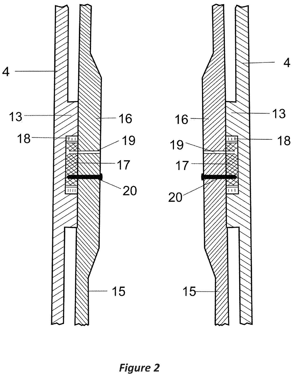
[0033]The structural details of the axial (FIG. 1A) and sleeve (FIG. 1B) segments of the short elbow part of the blade include the following: plant hub 1, which is connected to the main shaft of the engine, axial part cylindrical skeleton 3, sleeve segment cylindrical skeleton 4, axial and sleeve segment wall 12, top edge protuberance 5 for connecting the axial and sleeve segments, additional steel reinforcement of the edge and wall on the inside of the bend 6, edge holes 10, sleeve segment annular supports 13, and sleeve segment face end 14 for connection to the wing-shaped blade.

[0034]The axial segment has a hollow cylindrical shape (FIG. 1A), and is connected by bolts (not shown) to the wall of wind plant hub opening 9. The end of the axial part facing the bend has an elliptical shape, obliquely canted along the half-arc line between the axial line of the axial and sleeve parts running through their intersection point. The slope is directed outward from the direction of rotation ...


PUM


Abstract

A wind wheel includes a main shaft, a wind plant hub, and a plurality of blades. Each blade includes a short elbow part with axial and sleeve segments connected at 30°-45° angle and a long wing-shaped part, connected to the sleeve segment with an end shaft and by support devices with bearings. The short elbow part is made of steel, and is a distance of 1.5-5 meters or 0.20-1.5 meters from a connection thereof to the hub, and at a juncture of the axial and sleeve segments has a 10°-80° elbow bend opposite a direction of rotation of the wind wheel. The sleeve segment of the short elbow part has a cylindrical skeleton with three double support rings and is connected to the wing-shaped part of the blade, a root end of which is supplied with a hollow steel shaft with three removable protuberances with the bearings.

Description

CROSS-REFERENCE TO RELATED APPLICATION[0001]This application is a U.S. National Stage application of International Application No. PCT / KZ2018 / 000003, filed Jan. 23, 2018, which claims priority to KZ Patent Application No. 2017 / 0125.1, filed Feb. 14, 2017, the contents of each of which are hereby incorporated herein by reference.BACKGROUNDField of the Invention[0002]The invention relates to wind power, specifically the use of wind energy to generate power using horizontal-axis turbines in low-, medium-, and high-capacity wind power plants using a three-bladed rotor. The principal element of the wind power plant for converting the kinetic energy of a wind stream is the design features of the wind wheel.Background of the Invention[0003]Conventional wind wheels for power plants have a horizontal axis of rotation (EP 1923567A2 of May 21, 2008, F03D 1 / 06), in which the blade handle is mounted with an 8-10° windward inclination from the vertical plane, which prevents destruction of the bla...

Claims


Application Information

Patent Timeline
Patent Type & Authority Patents(United States)
IPC IPC(8): F03D1/06
CPCF03D1/0675F03D1/0658F05B2250/36F05B2250/314F05B2260/79F05B2260/70Y02E10/72
Inventor SHAIKENOV, BLOKSHAIKENOV, YERZHAN BLOKOVICH
Owner SHAIKENOV BLOK
Why Eureka
Try Eureka