Drive unit for a strapping device

a technology of drive unit and strapping device, which is applied in the direction of bundling articles, bundling machine details, transportation and packaging, etc., can solve the problems of vibration damped, higher risk of rupturing, and melting of thermoplastic tape locally, so as to reduce the number of components, less precision, and cost-effective

Active Publication Date: 2021-01-05
FROMM HLDG
View PDF10 Cites 2 Cited by
  • Summary
  • Abstract
  • Description
  • Claims
  • Application Information

AI Technical Summary

Benefits of technology

[0022]In order to keep the production outlay to a low level here, the casing extension, which is provided with the axial fixing means, is produced in the form of a separate component and then fitted on the casing of the electric motor. The casing of the electric motor itself can then be produced with a lesser amount of precision and therefore more cost-effectively.
[0023]In embodiments, the casing extension is formed in one piece with the cover of the motor, as a result of which it is possible to reduce the number of components which have to be produced for the drive unit.

Problems solved by technology

This vibration gives rise to relative movement between the upper tape and lower tape which, on account of the resulting friction, leads to the thermoweldable plastic tape melting locally.
Such relatively small dimensioning, however, results in a higher risk of rupturing.
In order to avoid these double fits and the resulting stressing, it has been proposed that in particular the rolling-contact bearings should be mounted in rubber, this also resulting in vibrations being damped.
It has now been found, however, that, in the case of the strapping devices which have been known up until now, the electric motor used resulted in damage to the shaft ends of the electric motor or to the rolling-contact bearings with which the motor shaft is mounted in the motor housing.
It is assumed that this damage is the result of tilting moments and accompanying pitching movements which occur in the electric motor when the latter starts up, brakes or is reversed.
While electric motors are produced in large numbers, and are therefore available in the form of a finished unit comprising a rotor, stator and a surrounding casing with covers, pneumatic motors are produced in a product-specific manner and, unlike electric motors, cannot be inserted for example into a divided housing; rather, they have to be inserted into joint-free accommodating bores integrated in a strapping device.

Method used


Image

  • Drive unit for a strapping device
  • Drive unit for a strapping device
  • Drive unit for a strapping device

Examples


Embodiment Construction

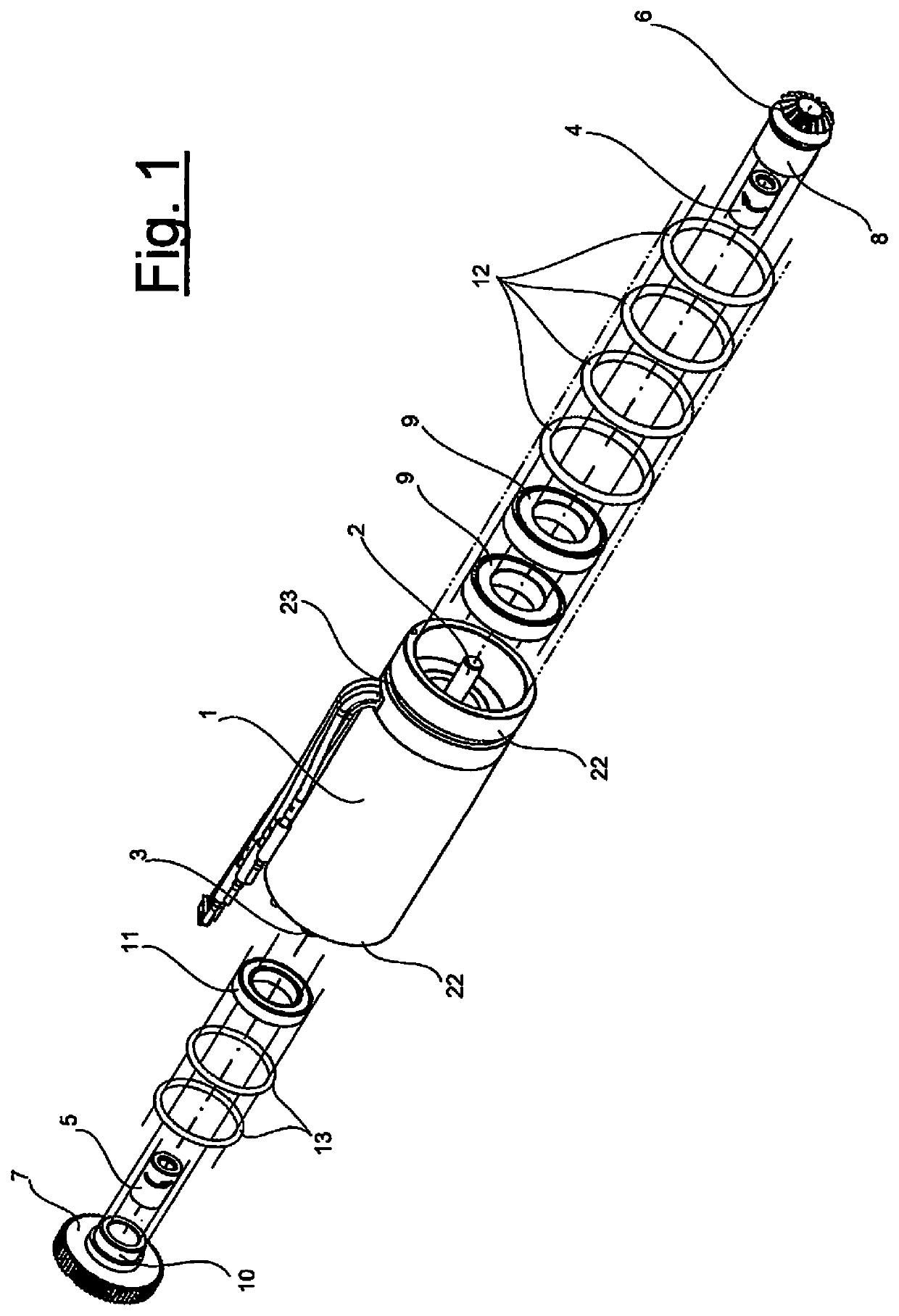
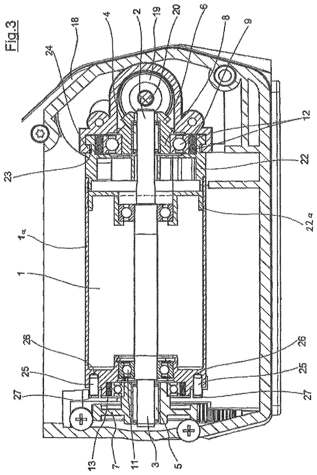
[0032]The figure shows an electric motor 1, which is driven electrically via a (storage) battery (not illustrated), wherein the motor shaft, which is connected to the rotor of the electric motor, has its two ends 2, 3 projecting out at opposite ends of the electric motor 1. Seated at said shaft ends are freewheels 4, 5, which transmit a rotary movement of the shaft ends in opposite directions.

[0033]These freewheels have, on the one hand, a bevel gear 6 and, on the other hand, a spur gear 7 positioned on them.

[0034]The bevel gear 6 has a shank 8, on which two rolling-contact bearings 9 are seated. In the same way, the spur gear 7 has a collar 10, on which a rolling-contact bearing 11 is seated.

[0035]Rubber buffers in the form of O rings 12 and 13 are pushed onto the aforementioned rolling-contact bearings 9 and 11, respectively.

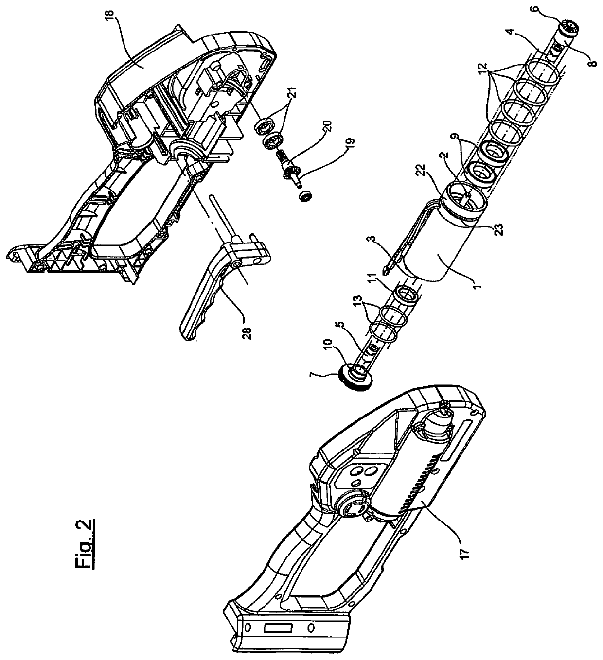
[0036]Also evident in FIG. 4 is a torque support 14, which is screwed firmly on the electric motor 1, via screws 15, by means of a flange disk 16.

[0037]The as...


PUM


Abstract

A drive unit for a strapping device strapping an item to be packed with a plastic tape which is laid around it includes a motorized tensioning device and a motorized welding device for the plastic tape. The tensioning and welding device can be driven by the same electric motor which can be brought alternatively into an operative connection with the devices with freewheels connected therebetween. A problem has occurred in drive units of this type that they are relatively complicated to assembly and have problematic operational reliability under certain boundary conditions. To bypass these problems, the electric motor includes at least one shell extension which protrudes beyond it at one axial end with the result that the drive elements which have up to now been mounted separately in the housing of a strapping device can be supported directly on the electric motor which then acts as a drive unit.

Description

CROSS-REFERENCE TO RELATED APPLICATIONS[0001]This application is a National Phase Entry of PCT Patent Application No. PCT / EP2015 / 001526 filed Jul. 22, 2015, which claims the benefit of German Patent Application No. 10 2014 011 929.7, filed Aug. 14, 2014, the disclosure of each of these applications are expressly incorporated herein by reference in their entireties.BACKGROUNDTechnical Field[0002]The present disclosure relates to a packaging components, and more particularly, to a drive unit for a strapping device for strapping a package with a plastic tape positioned around the same.Description of Related Art[0003]The present disclosure relates to a drive unit for a strapping device for strapping a package with a plastic tape positioned around the same, having a motor-driven tensioning device and a motor-driven welding device for the plastic tape, wherein the tensioning and welding devices can be driven by the same electric motor, which, with the interposition of freewheels, can alte...

Claims


Application Information

Patent Timeline
Patent Type & Authority Patents(United States)
IPC IPC(8): B65B13/02B65B13/32B65B13/22B65B13/18B65B51/22
CPCB65B13/025B65B13/187B65B13/22B65B13/322B65B51/222B65B13/18
Inventor RAUCH, MANFRED
Owner FROMM HLDG
Why Eureka
Try Eureka