
High-speed, high-resolution electrophysiology in-vivo using conformal electronics

a conformal electronic and high-resolution technology, applied in the field of medical devices, can solve the problems of brittle mechanical properties associated with conventional ics that strictly exclude non-destructive, intimate integration, and prolong ep procedures, and achieve the effect of limiting the net leakage curren

Active Publication Date: 2021-02-16
THE BOARD OF TRUSTEES OF THE UNIV OF ILLINOIS +1
View PDF472 Cites 1 Cited by
  • Summary
  • Abstract
  • Description
  • Claims
  • Application Information

AI Technical Summary

Benefits of technology

[0012]The materials, physical dimensions and mechanical properties of the device, and components thereof, are selected in some embodiments to provide complete or partial electronic, optical, chemical and / or thermal isolation of the device from the tissue and / or biological environment useful for avoiding damage of the tissue during use. In an embodiment, for example, the barrier layer and the flexible or stretchable substrate limit a net leakage current from the electronic circuit to an amount which does not adversely affect the tissue. In an embodiment, for example, the barrier layer and the flexible or stretchable substrate limits heat transfer from the electronic circuit to the tissue in the biological environment to an amount that does not adversely affect the tissue in the biological environment.
[0061]In an aspect, the invention provides a device for interfacing with a tissue in a biological environment, the device comprising: (1) a flexible or stretchable substrate; (2) a stretchable or flexible array of light emitting diodes comprising a plurality of light emitting diodes in electrical communication with a plurality of stretchable or flexible electrical interconnects, the stretchable or flexible array of light emitting diodes supported by the flexible or stretchable substrate; and (3) a barrier layer encapsulating at least a portion of the stretchable or flexible array of light emitting diodes to limit a net leakage current from the stretchable or flexible array of light emitting diodes to the tissue to an amount that does not adversely affect the tissue; wherein the flexible or stretchable substrate, stretchable or flexible array of light emitting diodes and the barrier layer provide a net bending stiffness of the device low enough that the device establishes conformal contact with the tissue in the biological environment. In an embodiment, the device of this aspect is an implantable or skin mounted array of light emitting diodes. In an embodiment, for example, the stretchable or flexible array of light emitting diodes comprises a multilayer structure comprising a plurality of individually encapsulated LED array layers provided in a multilayer stacked geometry, for example, wherein 2 to 50 individually encapsulated LED array layers provided in a multilayer stacked geometry.

Problems solved by technology

The iterative nature of this approach prolongs EP procedures and impedes real time mapping of transient abnormal rhythms.
Despite explosive growth and innovation in the broader electronics industry, the key limitation of EP devices is that they have retained the simple electronics-tissue interface of their earliest predecessors of ˜40 years ago.
Unfortunately the planar shapes and rigid, brittle mechanical properties associated with conventional ICs strictly preclude their non-destructive, intimate integration with the curvilinear, soft surfaces of biological tissues.

Method used


Image

  • High-speed, high-resolution electrophysiology in-vivo using conformal electronics
  • High-speed, high-resolution electrophysiology in-vivo using conformal electronics
  • High-speed, high-resolution electrophysiology in-vivo using conformal electronics

Examples


example 1

d, High-Resolution Cardiac Electrophysiology In-Vivo Using Conformal Electronics

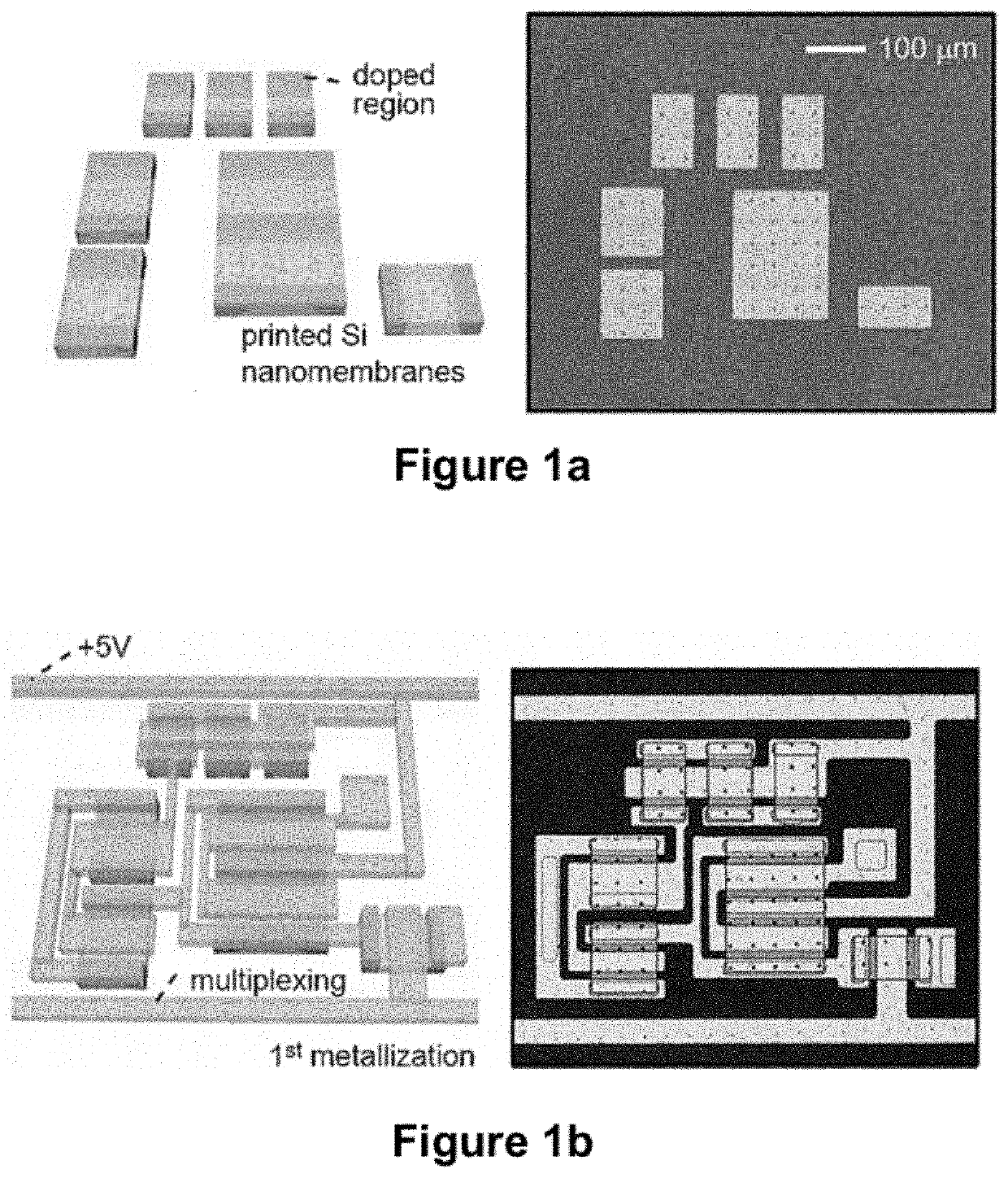
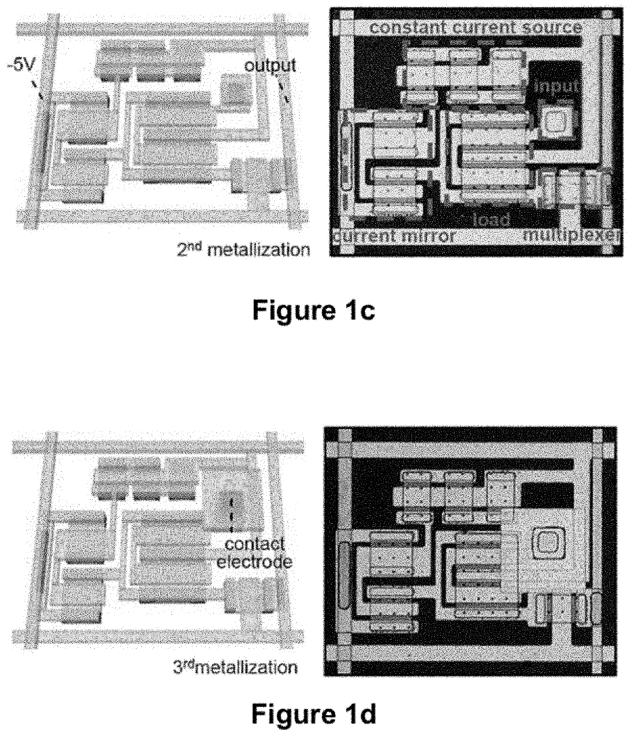
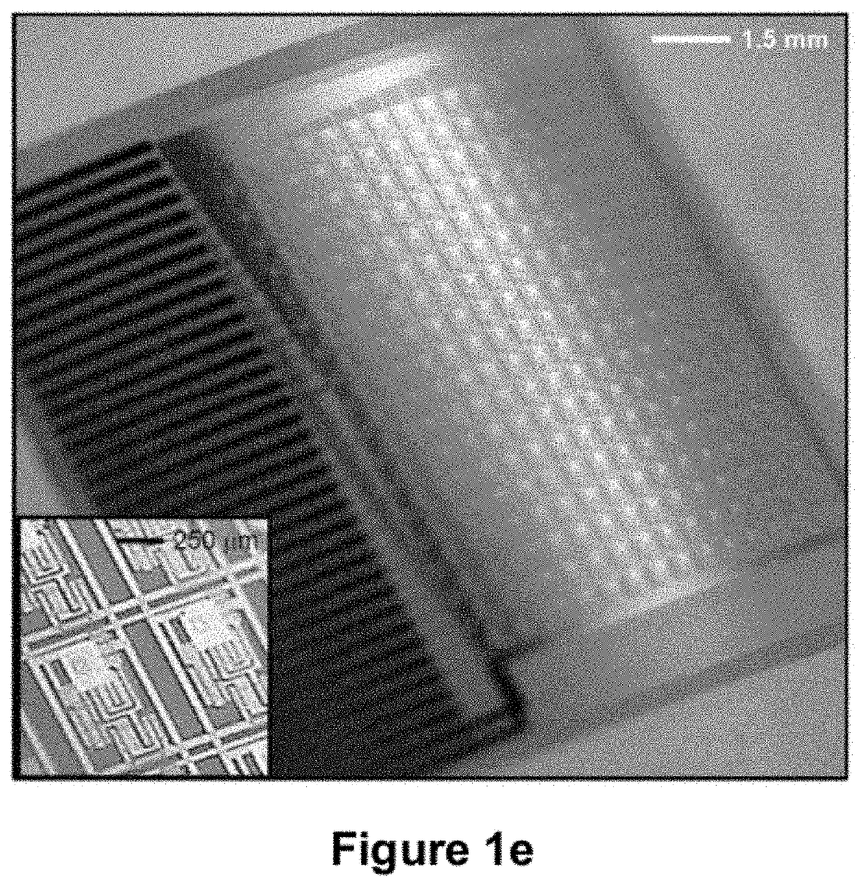
[0194]Mapping cardiac arrhythmias with standard, clinical electrophysiology (EP) devices can be a tedious, lengthy process, particularly over the epicardial surface. Probes with small numbers (4-10) of widely spaced (2-5 mm) passive electrodes sequentially record electrical activity from small areas of heart muscle as they are moved manually, point to point, across regions of interest. Because each electrode requires a separate connection to external processors, spatial resolution and mapping speed are limited by practical constraints on the number and configuration of electrodes and wires that can fit in the device. This example describes a high resolution, high speed system that eliminates these constraints. The device uses fully integrated, conformal electronic circuits (built with >2,000 single crystal silicon nanoribbon transistors) to simultaneously record from 288 multiplexed (16:1) channels, each...

example 2

r Encapsulation for Enhanced Moisture Barrier

[0249]One advantage achieved by encapsulation is prevention of leakage current from electronic circuitry to a surrounding conductive solution, such as saline solution, while the contact type metal electrode that is connected to the gate of load transistor is exposed to the surface to make a conformal and intimate contact to the curvilinear, soft cardiac tissue. This example describes a multilayer encapsulation structure to enhance prevention of leakage current.

[0250]Multiple Layer Structure with Mis-aligned Via Structure. The encapsulation can be a single polymer layer or in can be a multilayer structure. If a single polymer layer (e.g., ˜20 μm) is used, pinholes can form following a dry etching process for via interconnect due to incomplete masking. Such pinholes can be prevented, for example, if a photo-definable thick polymer, such as SU8, is used, since the etching process is not needed. For a one layer structure, a mis-aligned via st...

example 3

of a Conformal Electronic Device for Sensing or Actuation

[0259]FIG. 26A provides a schematic illustration of a cross sectional view of a conformal electronic device embodiment for sensing or actuation of a tissue in a biological environment. Conformable device 100 comprises flexible or stretchable substrate 110 supporting a flexible or stretchable electronic circuit comprising plurality of inorganic semiconductor circuit elements 120, such as electronic device components including sensors, actuators, electrode arrays, LED arrays, optical sources, integrated circuits, multiplexing circuits and / or amplifiers. Barrier layer 130 encapsulating at least a portion of the flexible or stretchable electronic circuit may provide a moisture barrier, a thermal barrier, an electromagnetic barrier, an electrical barrier, a magnetic barrier, a selectively permeable or impermeable barrier or any combination of these. In some embodiments, the flexible substrate, the flexible or stretchable electronic...


PUM


Abstract

Provided herein are biomedical devices and methods of making and using biomedical devices for sensing and actuation applications. For example, flexible and / or stretchable biomedical devices are provided including electronic devices useful for establishing in situ conformal contact with a tissue in a biological environment. The invention includes implantable electronic devices and devices administered to the surfaces(s) of a target tissue, for example, for obtaining electrophysiology data from a tissue such as cardiac, brain tissue or skin.

Description

CROSS REFERENCE TO RELATED APPLICATIONS[0001]This application claims the benefit of U.S. Provisional Application Nos. 61 / 286,921, 61 / 313,397 and 61 / 388,529 filed Dec. 16, 2009, Mar. 12, 2010 and Sep. 30, 2010, respectively, each of which is hereby incorporated by reference to the extent not inconsistent herewith.STATEMENT REGARDING FEDERALLY SPONSORED RESEARCH OR DEVELOPMENT[0002]This invention was made with United States governmental support from The U.S. Department of Energy under Award No. DEFG02-91 ER45439, the National Science Foundation under grant DMI-0328162, the U.S. Department of Energy under Award No. DE-FG02-07ER46471, the U.S. Army Research Laboratory and the U.S. Army Research Office under contract number W911 NF-07-1-0618, the National Institute of Neurological Disorders and Stroke (NINDS) under Award Nos. RO1-NS041811-04 and RO1-NS48598-01 and by the DARPA-DSO and the National Institutes of Health P41 Tissue Engineering Resource Center under award number P41 EB002520...

Claims


Application Information

Patent Timeline
Patent Type & Authority Patents(United States)
IPC IPC(8): A61B5/042A61N1/05H01L23/31A61B5/07H05K1/02A61B5/00A61N1/04H01L23/00H05K3/32H01L29/786H05K1/14H01L21/683H01L27/12A61N1/36A61B5/296
CPCA61B5/0422A61B5/076A61B5/6867A61N1/0472A61N1/05H01L23/3192H01L24/24H01L24/50H01L24/82H01L24/86H05K1/0283A61B2562/02A61B2562/066A61B2562/12A61B2562/164A61N1/0587A61N1/36002H01L21/6835H01L23/3121H01L27/1218H01L29/7869H01L29/78603H01L2221/6835H01L2221/68386H01L2224/24137H01L2224/793H01L2224/8685H01L2224/86203H01L2924/12036H01L2924/12041H01L2924/12043H01L2924/12044H01L2924/14H01L2924/15788H01L2924/19041H01L2924/3011H01L2924/3025H05K1/147H05K3/323H05K2201/09263A61B5/287A61N2005/0652A61N5/0622H01L2924/00
Inventor ROGERS, JOHN A.KIM, DAE HYEONGMOSS, JOSHUA D.CALLANS, DAVID J.LITT, BRIANVIVENTI, JONATHAN
Owner THE BOARD OF TRUSTEES OF THE UNIV OF ILLINOIS
Learn More