Intensity corrected magnetic resonance images

a magnetic resonance image and intensity correction technology, applied in the field of magnetic resonance imaging, to achieve the effect of comparing effectively and maximizing mutual information algorithms

Active Publication Date: 2021-02-16
KONINKLJIJKE PHILIPS NV
View PDF8 Cites 0 Cited by
  • Summary
  • Abstract
  • Description
  • Claims
  • Application Information

AI Technical Summary

Benefits of technology

[0012]This may have huge advantages when performing so called longitudinal studies where a series of magnetic resonance images from different times are examined. Making the intensity profiles of the magnetic resonance images more uniform may also increases the ability of automatic algorithms to correctly segment or analyze the series of magnetic resonance images.
[0044]Execution of the machine-executable instructions further cause the processor to calculate the at least one second corrected magnetic resonance image descriptive of the analysis region using the at least one second magnetic resonance image dataset and the at least one second intensity correction map.

Problems solved by technology

Bias field inhomogeneities can in particular cause difficulties when using automatic algorithms to segment or identify regions in magnetic resonance images.

Method used


Image

  • Intensity corrected magnetic resonance images
  • Intensity corrected magnetic resonance images
  • Intensity corrected magnetic resonance images

Examples


Embodiment Construction

[0065]Like numbered elements in these figures are either equivalent elements or perform the same function. Elements which have been discussed previously will not necessarily be discussed in later figures if the function is equivalent.

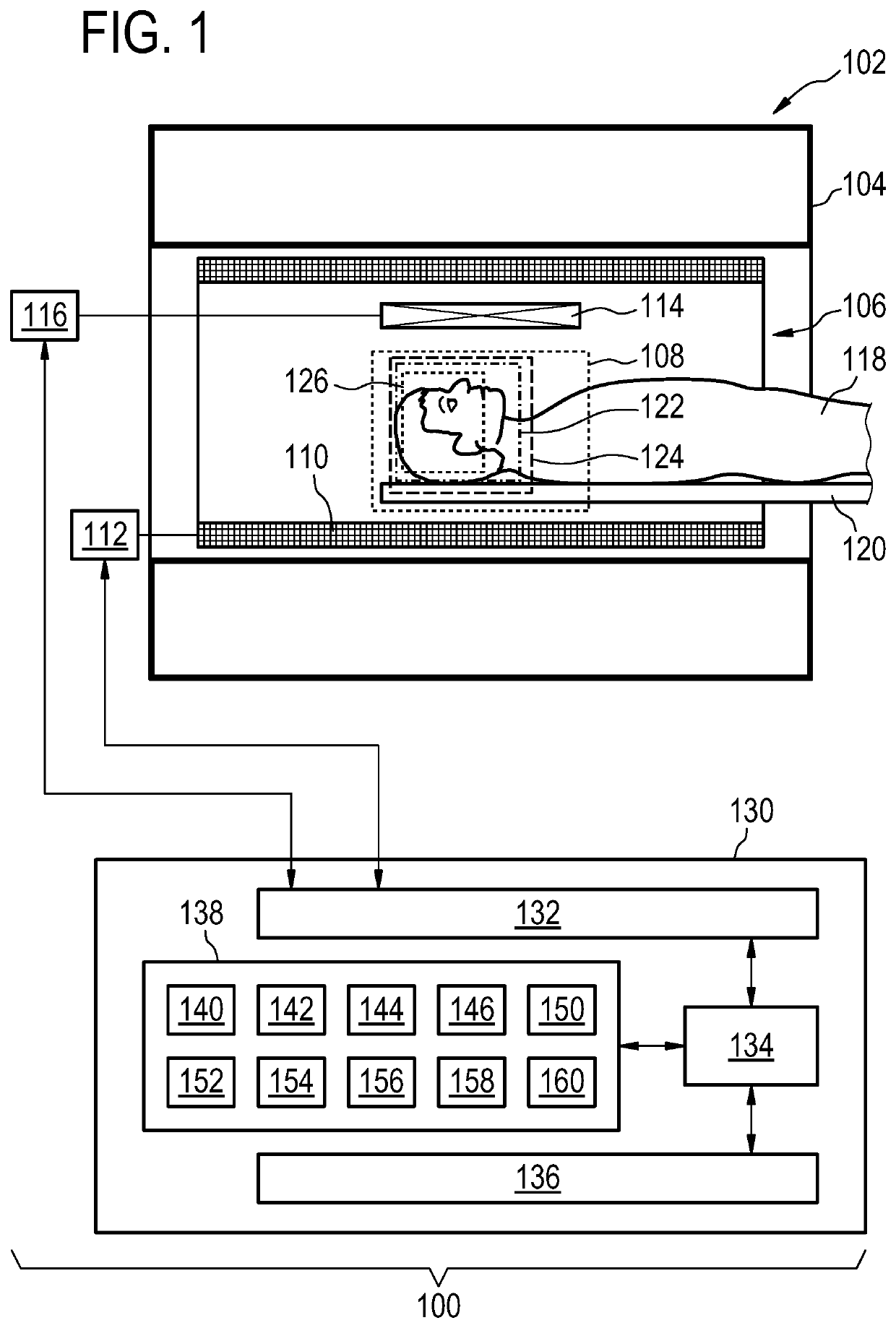
[0066]FIG. 1 illustrates an example of a medical instrument 100. In this example the medical instrument comprises a magnetic resonance imaging system 102 and a computer system 130. In some examples, the medical instrument 100 only comprises the computer system 130 or an equivalent controller. The magnetic resonance imaging system 102 comprises a magnet 104. The magnet 104 is a superconducting cylindrical type magnet 104 with a bore 106 through it. The use of different types of magnets is also possible. Inside the cryostat of the cylindrical magnet, there is a collection of superconducting coils. Within the bore 106 of the cylindrical magnet 104 there is an imaging zone 108 where the magnetic field is strong and uniform enough to perform magnetic resonan...


PUM


Abstract

The invention provides for a medical instrument (100) comprising a processor (134) and a memory (138) containing machine executable instructions (140). Execution of the machine executable instructions causes the processor to: receive (200) a first magnetic resonance image data set (146) descriptive of a first region of interest (122) of a subject (118) and receive (202) at least one second magnetic resonance image data set (152, 152′) descriptive of a second region of interest (124) of the subject. The first region of interest at least partially comprises the second region of interest. Execution of the machine executable instructions further cause the processor to receive (204) an analysis region (126) within both the first region of interest and within the second region of interest. Execution of the machine executable instructions further cause the processor to construct (206) a cost function comprising an intra-scan homogeneity measure separately for the first magnetic resonance image data set and separately for each of the at least one second magnetic resonance image data set. The cost function further comprises an inter-scan similarity measure calculated using both the first magnetic resonance image data set and each of the at least one second magnetic resonance image data set. Execution of the machine executable instructions further cause the processor to by performing an optimization (208) of the cost function by calculating a first intensity correction map (154) for the first magnetic resonance image data set using an intensity correction algorithm within the analysis region and at least one second intensity correction map (156) for each of the at least one second magnetic resonance image data set within the analysis region. Execution of the machine executable instructions further cause the processor to calculate (210) a first corrected magnetic resonance image (158) descriptive of the analysis region using the first magnetic resonance image data set and the first intensity correction map. Execution of the machine executable instructions further cause the processor to calculate (212) at least one second corrected magnetic resonance image (160) descriptive of the analysis region using the at least at least one second magnetic resonance image data set and the at least one second intensity correction map.

Description

CROSS REFERENCE TO RELATED APPLICATIONS[0001]This application is a U.S. national phase application of International Application No. PCT / EP2017 / 078833 filed on Nov. 10, 2017, which claims the benefit of EP Application Serial No. 16199279.9 filed on Nov. 17, 2016 and is incorporated herein by reference.FIELD OF THE INVENTION[0002]The invention relates to magnetic resonance imaging, in particular to the correction of intensity inhomogeneities for a series of magnetic resonance images.BACKGROUND OF THE INVENTION[0003]A large static magnetic field is used by Magnetic Resonance Imaging (MRI) scanners to align the nuclear spins of atoms as part of the procedure for producing images within the body of a patient. This large static magnetic field is referred to as the BO field or the main magnetic field.[0004]One method of spatially encoding is to use magnetic field gradient coils. Typically there are three coils which are used to generate three different gradient magnetic fields in three dif...

Claims


Application Information

Patent Timeline
Patent Type & Authority Patents(United States)
IPC IPC(8): G06K9/00G01R33/565G06T7/30G06T7/00G06T5/50
CPCG01R33/56572G01R33/5659G06T5/50G06T7/30G06T7/97G06T2207/10088G01R33/56G01R33/565
Inventor WENZEL, FABIANBERGTHOLDT, MARTINTHIELE, FRANK OLAF
Owner KONINKLJIJKE PHILIPS NV
Why Eureka
Try Eureka