Method and system for homogenizing diode laser pump arrays

a laser pump array and laser technology, applied in semiconductor lasers, instruments, optical elements, etc., can solve the problems of anisotropic (uneven) illumination of diode laser pump arrays, and achieve the effects of improving beam quality, uniform intensity profile, and high extraction efficiency

Active Publication Date: 2014-12-11
LAWRENCE LIVERMORE NAT SECURITY LLC
View PDF4 Cites 0 Cited by
  • Summary
  • Abstract
  • Description
  • Claims
  • Application Information

AI Technical Summary

Benefits of technology

[0012]Many benefits are achieved by way of the present invention over conventional techniques. For example, the present technique provides for homogenization of diode illumination, resulting in a uniform intensity profile, higher extraction efficiency from solid state amplifiers and laser gain media, and improved beam quality for the output of the solid state amplifiers. Moreover, transfer efficiency provided by embodiments of the present invention can exceed 98%. Embodiments of the present invention are applicable to high power solid state amplifiers as well as solid state lasers. Additionally, embodiments of the present invention provide a method of manufacturing diffractive optics with smooth phase profiles, thereby improving homogenization and solid state amplifier / laser efficiency. Embodiments of the present invention homogenize the diode illumination, leading to even illumination and improved beam quality in high average power diode pumped solid state lasers. Even illumination enables improved laser extraction efficiency and a uniform thermal load which minimizes thermally induced wavefront distortions. The improved beam quality and wavefront further serve to enhance the reliability of the laser device since the fluence or intensity loading of optics in the system are lower relative to the laser induced optical damage threshold. These and other embodiments of the invention along with many of its advantages and features are described in more detail in conjunction with the text below and attached figures.

Problems solved by technology

Although diode pumping offers dramatically increased efficiency, longevity, and decreased heat loading relative to flash lamp pumping, diode laser pump arrays typically provide anisotropic (uneven) illumination.

Method used


Image

  • Method and system for homogenizing diode laser pump arrays
  • Method and system for homogenizing diode laser pump arrays
  • Method and system for homogenizing diode laser pump arrays

Examples


Embodiment Construction

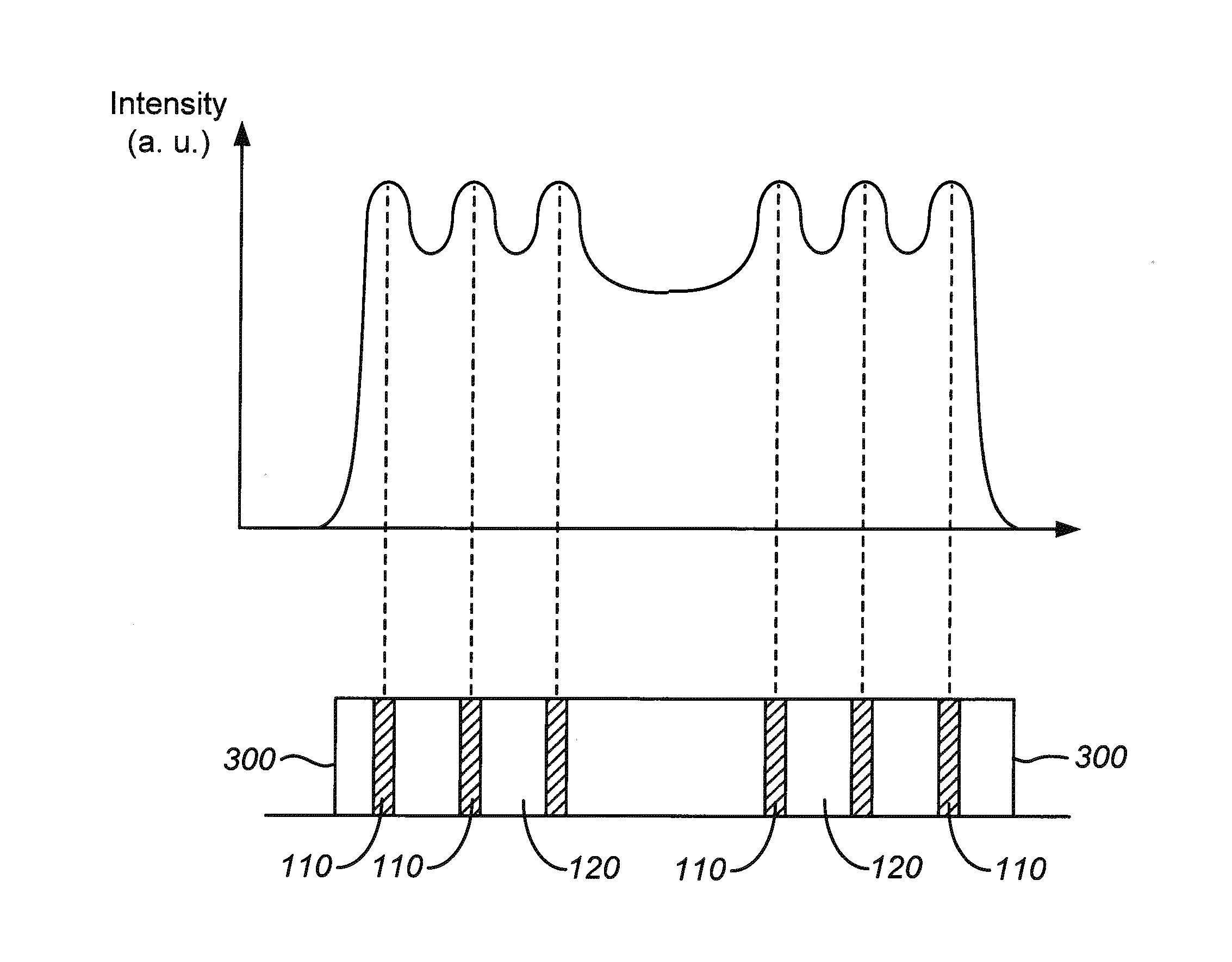
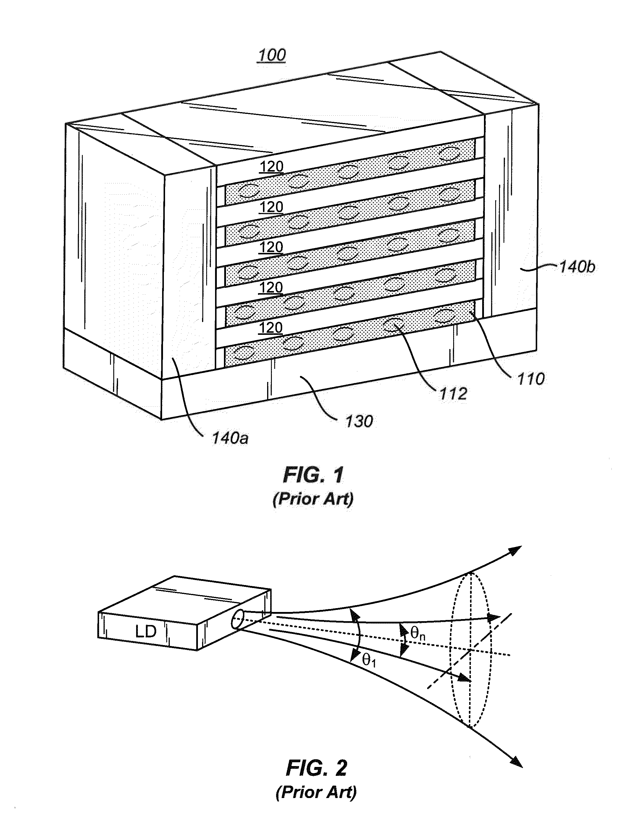
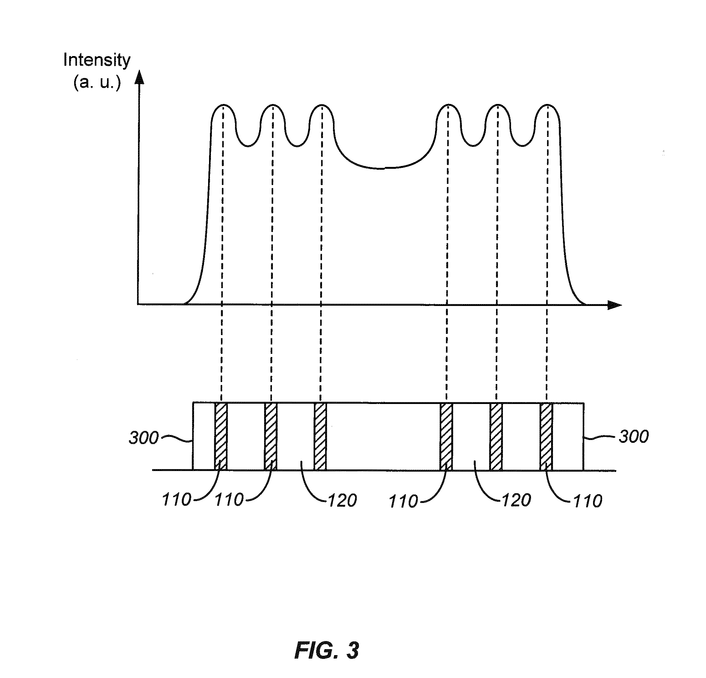
[0024]FIG. 3 is a simplified plot of laser intensity as a function of position for two modules of diode laser arrays. For FIG. 3, two modules 300 are illustrated, each module including an array of laser bars 110 separated by heat spreaders 120. The modules can be similar to the diode laser pump array 100 illustrated in FIG. 1. Even if the modules are collimated using lenslet arrays, the intensity profile measured vertically down the module 300 will be non-uniform. As shown in FIG. 3, the intensity profile has peaks associated with the laser bars 110, valleys associated with the heat spreaders 120 between the laser bars, and a larger valley between adjacent modules. The intensity profile illustrated in FIG. 3 is undesirable since such a pump intensity profile will result in non-uniformity in the gain profile of the amplifier. Non-uniformity in the gain profile of the amplifier (or laser) results in lower amplifier efficiency and degraded beam quality.

[0025]To overcome the non-uniform...


PUM

PropertyMeasurementUnit
diameteraaaaaaaaaa
temperatureaaaaaaaaaa
grayscale intensityaaaaaaaaaa

Abstract

An optical amplifier system includes a diode pump array including a plurality of semiconductor diode laser bars disposed in an array configuration and characterized by a periodic distance between adjacent semiconductor diode laser bars. The periodic distance is measured in a first direction perpendicular to each of the plurality of semiconductor diode laser bars. The diode pump array provides a pump output propagating along an optical path and characterized by a first intensity profile measured as a function of the first direction and having a variation greater than 10%. The optical amplifier system also includes a diffractive optic disposed along the optical path. The diffractive optic includes a photo-thermo-refractive glass member. The optical amplifier system further includes an amplifier slab having an input face and position along the optical path and separated from the diffractive optic by a predetermined distance. A second intensity profile measured at the input face of the amplifier slab as a function of the first direction has a variation less than 10%.

Description

CROSS-REFERENCES TO RELATED APPLICATIONS[0001]The following two regular U.S. patent applications (including this one) are being filed concurrently, and the entire disclosure of the other application is incorporated by reference into this application for all purposes:[0002]Application Ser. No. ______, filed Aug. 19, 2009, entitled “Method and System for Homogenizing Diode Laser Pump Arrays” (Attorney Docket No. 027512-001300US); and[0003]Application Ser. No. ______, filed Aug. 19, 2009, entitled “Diffractive Laser Beam Homogenizer including a Photo-Active Material and Method of Fabricating the Same” (Attorney Docket No. 027512-001400US).STATEMENT AS TO RIGHTS TO INVENTIONS MADE UNDER FEDERALLY SPONSORED RESEARCH OR DEVELOPMENT[0004]The United States Government has rights in this invention pursuant to Contract No. DE-AC52-07NA27344 between the United States Department of Energy and Lawrence Livermore National Security, LLC.BACKGROUND OF THE INVENTION[0005]In high average power diode p...

Claims


Application Information

Patent Timeline
Patent Type & Authority Applications(United States)
IPC IPC(8): H01S5/04
CPCH01S5/041G02B5/1857G02B27/0927G02B27/0944H01S3/005H01S3/10023H01S3/2308G02B19/0057G02B19/0095G02B19/0014H01S3/094049H01S3/094053H01S5/02476H01S5/4012H01S5/405H01S3/0606Y10T29/49G02B27/0922
Inventor BAYRAMIAN, ANDREW JAMES
Owner LAWRENCE LIVERMORE NAT SECURITY LLC
Why Eureka
Try Eureka