Laminate-type power storage element

a power storage element and laminate-type technology, applied in sustainable manufacturing/processing, non-aqueous electrolyte cells, batteries, etc., can solve problems such as liquid leakage, data reading and writing errors, etc., to reduce the electrical performance of laminate-type power storage elements, increase manufacturing costs, and tighten the permissible range of alignment errors

Active Publication Date: 2021-02-16
FDK CORP
View PDF9 Cites 1 Cited by
  • Summary
  • Abstract
  • Description
  • Claims
  • Application Information

AI Technical Summary

Benefits of technology

[0014]Conceivably, a configuration having no separation between the peripheral edge region 12 of the exterior body 11 and the region of the exterior body 11 where the electrode body 10 is possible, to preemptively eliminate a region where creases might be generated. However, in such a configuration, the laminated films 11a, 11b and the electrode body 10 must be precisely aligned when the exterior body 11 is sealed, because any misalignment results in a portion of the electrode body 10 intruding into the peripheral edge region 12 during sealing. This gives rise to the possibility of liquid leakage due to insufficient sealing or insufficient sealing strength. Moreover, there would be a substantially right-angled step at the inner peripheral edges of the peripheral edge region 12 due to the presence of the electrode body 10, which is thicker than the laminated films 11a, 11b. A force in a direction to separate the two sheets of laminated film 11a, 11b would accordingly be continuously applied at the peripheral edge region 12. This would result in the possibility of sealing at the peripheral edge region 12 of the exterior body 11 being broken by impact or the like. In particular, in a laminate-type power storage element 1 that has a small surface area for use as a power source of an IC card, the surface area of the peripheral edge region 12 is also small. This means that there is an extremely tight permissible range for alignment error, and the sealing strength of the exterior body 11 is also smaller than that of other laminate-type power storage elements 1. Thus, in a small laminate-type power storage element 1, there is a greater need to provide some clearance between the peripheral edge region 12 and the electrode body 10.
[0015]Accordingly, there is a need for some form of configuration and structure of a laminate-type power storage element such that creases are less likely to be generated in the exterior body due to bending. Adopting such a configuration and structure should obviously not decrease the electrical performance of the laminate-type power storage element, nor increase the manufacturing costs thereof. An object of the disclosure is accordingly to provide a laminate-type power storage element in which creases are less likely to be generated in an exterior body by bending, while maintaining good electrical performance and competitive manufacturing costs.

Problems solved by technology

When the laminate-type power storage element 1 is incorporated into an IC card, creases generated in the laminate-type power storage element 1 can cause problems.
Due to IC cards being inserted into card slots when used in data reading devices, deformation of IC cards results in errors in data reading and writing, and in some cases the IC cards might no longer being insertable into card slots, or an inserted IC card cannot be removed.
This gives rise to the possibility of liquid leakage due to insufficient sealing or insufficient sealing strength.

Method used


Image

  • Laminate-type power storage element
  • Laminate-type power storage element
  • Laminate-type power storage element

Examples


embodiments

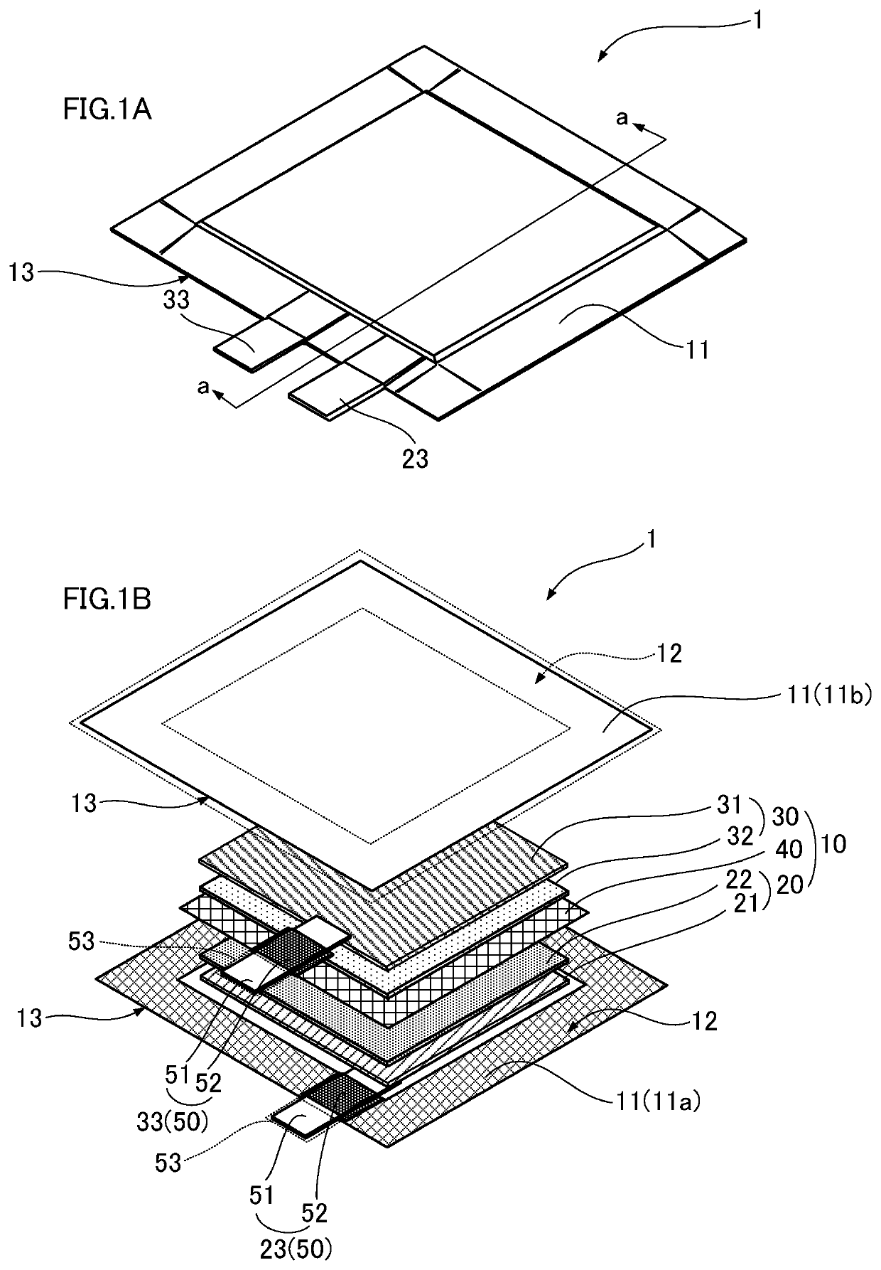
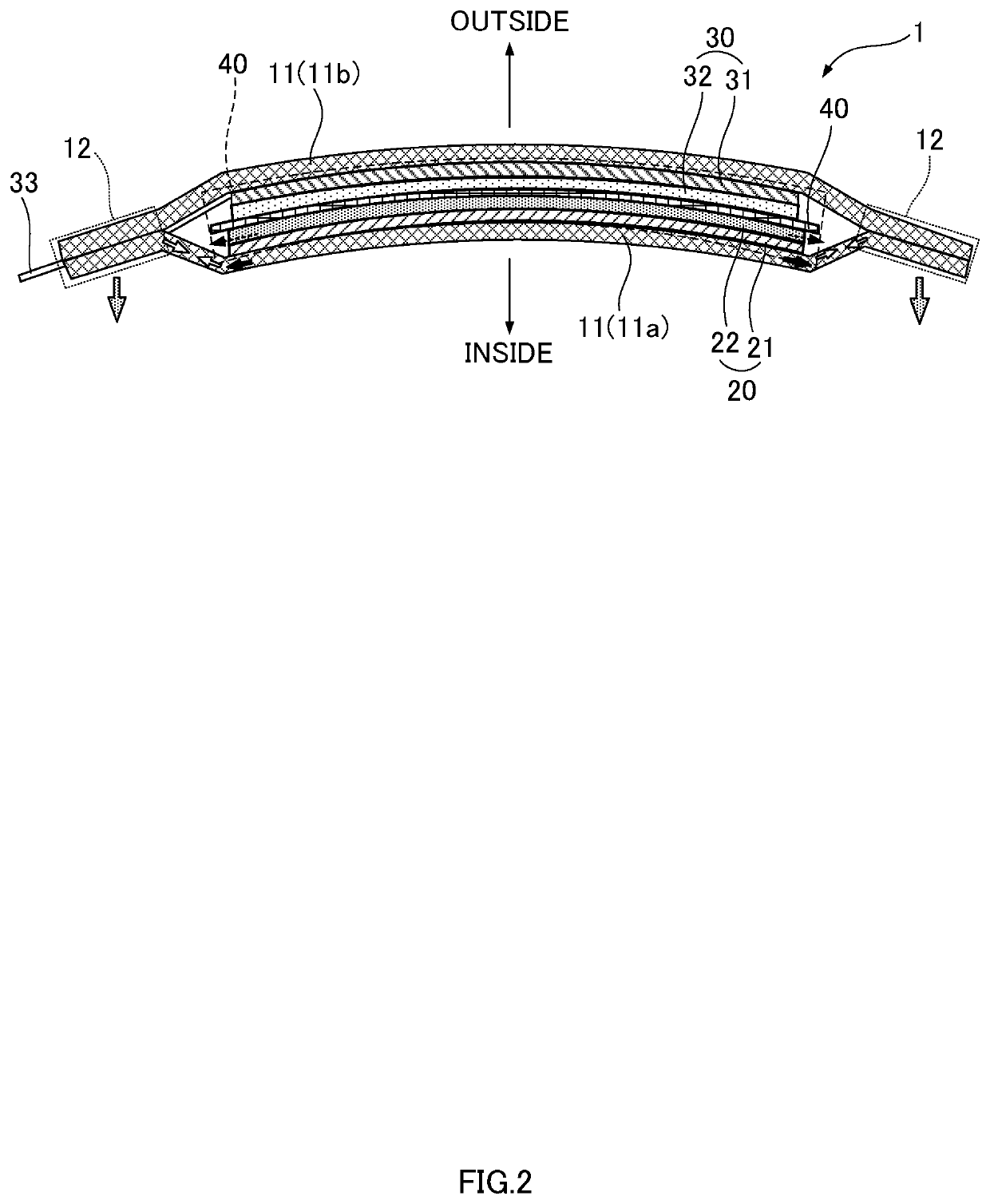
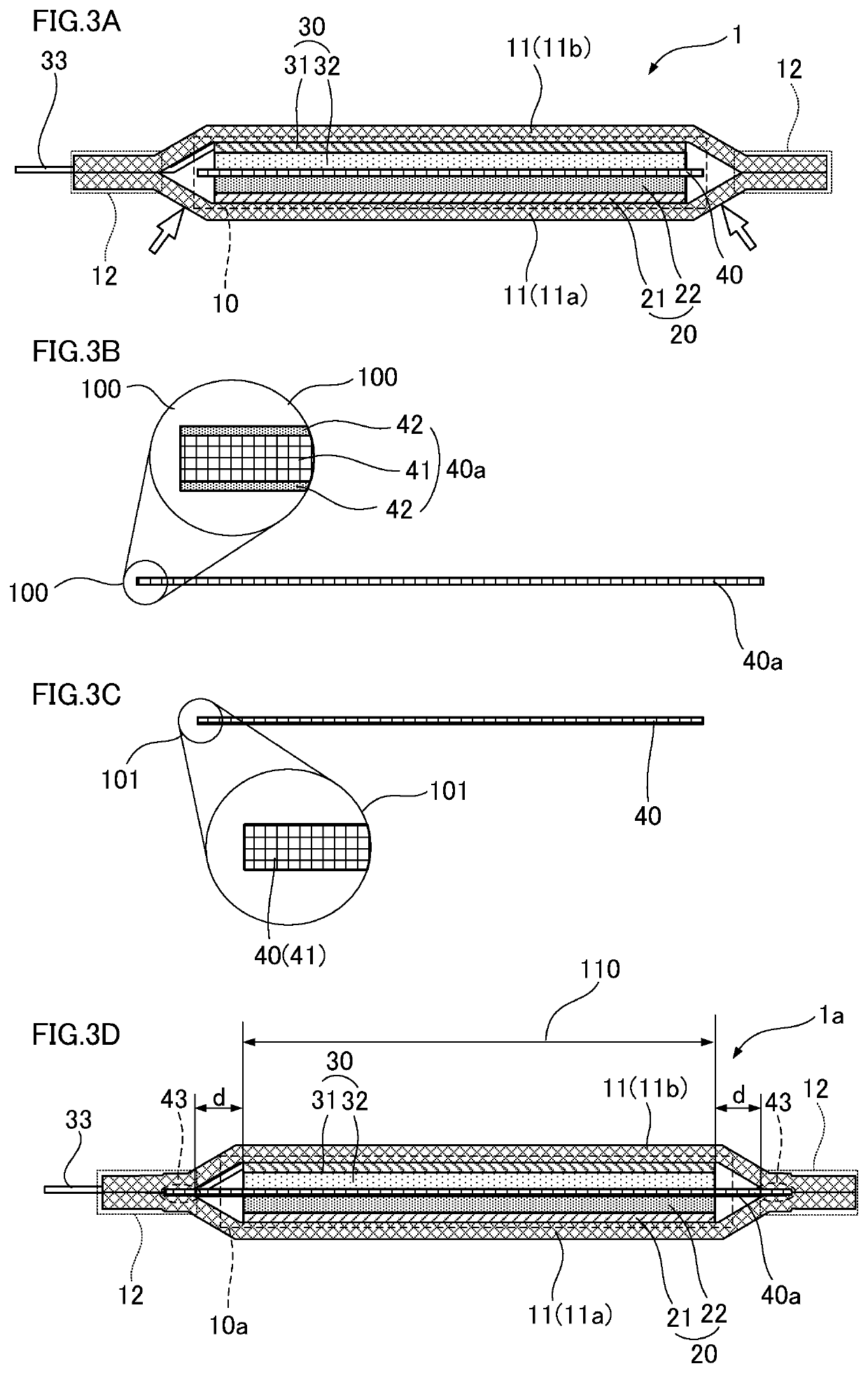
[0032]FIG. 3D illustrates the internal structure of a laminate-type power storage element 1a according to an embodiment of the present disclosure. In contrast, FIG. 3A is a cross-section illustrating the internal structure of the laminate-type power storage element 1 illustrated in FIG. 1. FIG. 3B is a cross-section illustrating a separator 40a employed in the laminate-type power storage element 1a according to an embodiment of the present disclosure. Similarly, FIG. 3C is a cross-section illustrating a structure of the separator 40 employed in the laminate-type power storage element 1.

[0033]As illustrated in FIG. 3D, the laminate-type power storage element 1a according to an embodiment of the present disclosure includes an electrode body 10a configured by a sheet-shaped positive electrode 20 and a sheet-shaped negative electrode 30 stacked on either side of the separator 40a. The electrode body 10a is encapsulated inside an exterior body 11, together with an electrolyte.

[0034]The e...


PUM

PropertyMeasurementUnit
thicknessaaaaaaaaaa
temperatureaaaaaaaaaa
melting pointaaaaaaaaaa

Abstract

A laminate-type power storage element includes a flat plate-shaped electrode body and an exterior body. The electrode body is configured by stacking a sheet-shaped positive electrode and a sheet-shaped negative electrode on either side of a separator. The exterior body is formed in a flattened bag-shape by thermocompression bonding peripheral edge regions of two opposing laminated films, to seal the electrode body inside the flattened bag-shape of the exterior body together with an electrolyte. The separator has a sheet-shaped substrate and at least one bonding layer formed on at least one surface of the substrate. A peripheral edge portion of the separator is sandwiched between and bonded by the two laminated films at a peripheral inside of the peripheral edge regions of the two laminated films.

Description

CROSS-REFERENCE TO RELATED APPLICATION[0001]The present application claims priority pursuant to 35 U.S.C.§ 119 to Japanese Patent Application No. 2017-099490 filed on May 19, 2017 in the Japan Patent Office, the entire disclosure of which is hereby incorporated herein by reference.BACKGROUNDTechnical Field[0002]The present disclosure relates to a laminate-type power storage element.Background Art[0003]Some electronic devices are extremely thin (also referred to below as thin-type electronic devices) while still including an in-built power source, such as IC cards incorporating one-time password functionality and a display, IC cards with an attached display, and tags and tokens (one-time password generators). Laminate-type power storage elements that are appropriate for downsizing and thinning are often employed as power sources in such thin-type electronic devices.SUMMARY[0004]A laminate-type power storage element 1 is illustrated in FIGS. 1A and 1B. FIG. 1A illustrates the external...

Claims


Application Information

Patent Timeline
Patent Type & Authority Patents(United States)
IPC IPC(8): H01M2/08H01M6/16H01M2/16H01M10/0525H01M10/0585H01M2/02H01M10/42H01M50/105H01M50/119H01M50/121H01M50/122H01M50/126H01M50/186H01M50/193H01M50/417H01M50/426H01M50/451H01M50/457
CPCH01M2/1653H01M2/0207H01M2/0275H01M2/0287H01M2/08H01M2/162H01M2/1686H01M6/16H01M10/0525H01M10/0585H01M10/4235H01M2220/30Y02E60/10H01M50/124H01M50/44Y02P70/50H01M50/417H01M50/105H01M50/121H01M50/186H01M50/457H01M50/193H01M50/126H01M50/451H01M50/426H01M50/119H01M50/122
Inventor IIDA, YUYAEGAWA, YASUAKIHIRATA, DAISUKEITO, RYUJIYAMAMOTO, AKIHIRO
Owner FDK CORP
Why Eureka
Try Eureka