
Method and apparatus for testing the blowout preventer (BOP) on a drilling rig

a blowout preventer and drilling rig technology, applied in the field of methods and apparatuses for testing the blowout preventer (bop) piping system, can solve the problems of preventing the integrity test from being completed, incomplete sealing of the valve, and wasting time and money, so as to reduce the number of false alarms, and improve the signal-to-noise ratio of the two-valve acoustic system

Active Publication Date: 2021-03-02
VISTA RES INC
View PDF4 Cites 0 Cited by
  • Summary
  • Abstract
  • Description
  • Claims
  • Application Information

AI Technical Summary

Benefits of technology

[0022]The preferred embodiment of the present invention is comprised of (1) a pressure testing system to test the BOP system or portions of the BOP system for integrity and (2) an acoustic valve measurement system to determine whether or not each valve that is closed for the pressure test is actually completely closed. The pressure testing system is used to test the BOP system or portions of the BOP system for integrity after verifying with an acoustic measurement system that all of the valves closed to isolate and pressurize that portion of the BOP system being tested are completely closed, and if not, to identify which valves are not completely closed and need to be closed to perform a test. As an alternative embodiment, a constant-pressure, volumetric measurement system can be used in conjunction with the acoustic system to quantify the flow across a valve that is not closed and to verify that the flow rate is zero when the valve is believed to be closed. If the measured flow is due to an incompletely closed valve, then this flow will be decreased or eliminated as the valve is more completely closed. Because a constant-pressure volumetric system can detect smaller flows than an acoustic system, the use of the volumetric system with the acoustic system further reduces the number of false alarms due to incompletely closed valves over that of an acoustic system alone. The constant-pressure, volumetric system will also detect any residual flow not associated with an incompletely sealed valve, and as an alternative embodiment, a constant-pressure volumetric testing system can be used instead of a pressure testing system for testing a portion or all of the BOP system for leaks. In this test, the pressure is maintained at the test pressure and the volume changes, which would result in a pressure drop, are measured directly and can be converted to an equivalent pressure drop, if necessary.
[0023]The acoustic valve measurement system provides a method to allow the BOP system to be pressure tested (or volumetrically tested) more efficiently and may reduce the number of pressure tests into sub-configuration that is currently required to complete a test of the entire BOP system, because the potential of a failed pressure test due to one or more incompletely sealed valves can be identified and minimized or eliminated before a test is performed.
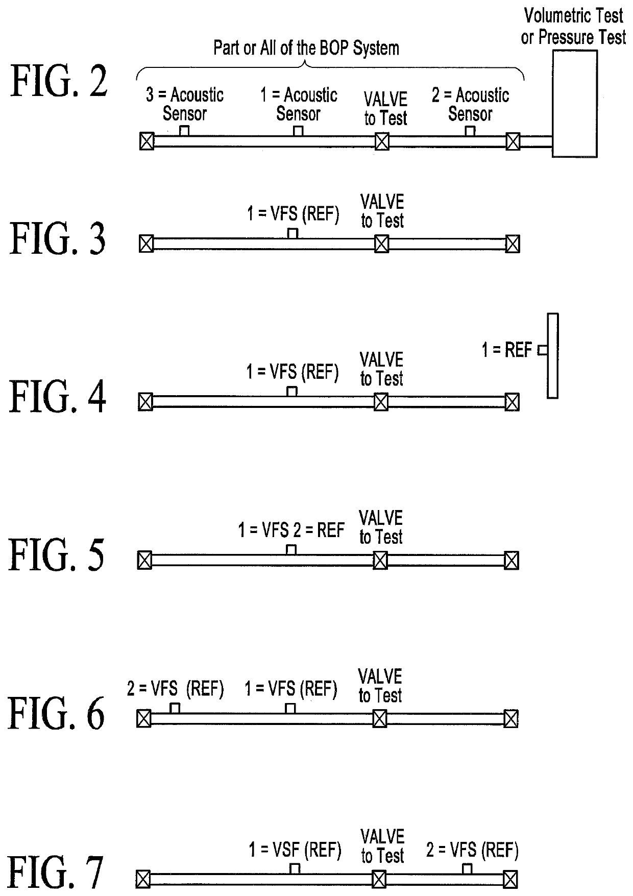
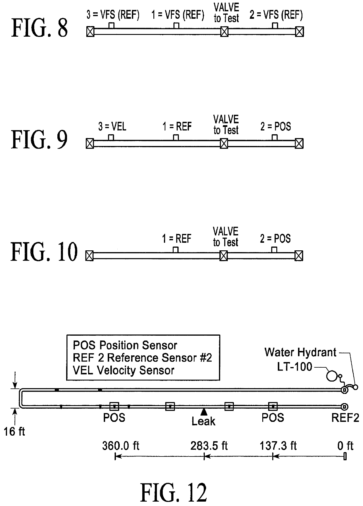
[0024]As illustrated for a simple pipe and valve configuration in FIG. 2, the preferred embodiment of the valve measurement system is comprised of two acoustic sensors mounted on the outside of the pipe with one sensor on either side of the valve. Acoustic sensors 1 and 2 are preferred, but acoustic sensors 3 and 2 will also work well. In addition, acoustic sensors 1 and 3, although they do not bracket the valve can also be used. As an alternative embodiment, the valve measurement system can be implemented with only one acoustic sensor positioned close enough to a valve that is not completely closed to detect any flow noise produced by that valve, but if flow noise from a valve is detected, it is not possible to say with certainty that it is the valve closest to the acoustic sensor that is not completely closed. With two or more acoustic sensors, where at least one acoustic sensor is located on either side of the valve, a definitive statement about the status of the valve that is bracketed by the acoustic sensors can be made, because the source of the valve flow signal can be “located” between the two sensors. In addition, the signal-to-noise ratio (SNR) of the two-valve acoustic system is significantly higher than a one-valve acoustic system. An accurate location estimate indicates that the bracketed valve is producing the valve flow signal. Once this bracketed valve is closed, another acoustic test will determine if other valves may also be incompletely closed. As another alternative embodiment, a third or fourth acoustic sensor can be mounted on the piping leading into the valve but at a known separation distance from each sensor bracketing the valve. The two acoustic sensors on each side of the valve (not bracketing the valve) can be used to detect a valve flow and to compute the velocity of the flow noise propagating through the piping, which leads to more accurate location of the valve between the two acoustic sensors bracketing the valve. They can also be used to determine from which direction a valve flow signal is coming from. To compute the propagation velocity requires that the distance between the acoustic sensors be known. The most reliable verification that a valve with bracketing acoustic sensors is completely sealed requires that the distance between two acoustic sensors bracketing the valve and from each sensor to the valve be known. However, such verification can also be accurately performed without knowing these distances.

Problems solved by technology

Any drop in pressure that exceeds some specified threshold value is indicative of an integrity problem.
Any valves that do not completely seal can be mistaken for a leak (i.e., a false alarm) or prevent an integrity test from being completed.
To mitigate these false alarms and incompletely sealed valves can be an extremely time-consuming and expensive process, because, first, it must be determined that a valve is not sealed and is the source of the pressure drop rather than a leak from a pipe flange, and second, if the pressure drop is due to an incompletely closed valve, then it must be determined which valve or valves are not sealed.
If a pressure loss occurs, then all of the valves are checked to insure they are closed, but this is a challenging task and is generally done by either re-opening and re-closing each valve to make sure they are closed and / or further tightening each valve.
This is time consuming, because the only way to determine whether or not the valve check was successful was to repeat the pressure test.
Simply reclosing the valve or more tightly closing the valve is no assurance that the valve is actually closed, because debris, grit, sand, and nicks in the valve may prevent a complete seal.
This approach will not work well, because there are a variety of sources of background noise present on a drilling rig that cannot be easily or safely eliminated and that could easily mask the valve flow signal.
One type is background noise that emanates from a single location or a single source.
This can not only mask the valve flow signal, but it can also be mistaken for a valve flow signal or a leak.
These sources of noise can be very large, much larger than the valve flow signal to be detected.
In general, simple acoustic listening systems do not have and do not use noise cancellation or advanced signal processing methods as described herein and none are currently used as part of BOP testing.
Another type of background noise is broadband noise that occurs at all frequency bands, including the valve flow signal bands.
If this level of noise is larger than the valve flow signal or a leak, it can mask the valve flow signal or a leak, and as indicated above, acoustic listening methods will not work, unless advanced signal processing is used.
This can be a challenging problem if the leaks are small or if tests are done at night or in inclement weather.
Valve closure problems are even more difficult to resolve.
Because of this testing significantly impacts operations and results in a loss of income, quicker methods of testing are needed.
The use of such acoustic systems, however, is not currently being done as part of the pressure test.
However, acoustic measurement systems for verifying valve closure have not been used or integrated together with a constant-pressure volumetric leak detection system when testing a BOP System for integrity, where a volumetric system can be used to quantify the flow rate across an incompletely seal valve.

Method used


Image

  • Method and apparatus for testing the blowout preventer (BOP) on a drilling rig
  • Method and apparatus for testing the blowout preventer (BOP) on a drilling rig
  • Method and apparatus for testing the blowout preventer (BOP) on a drilling rig

Examples


Embodiment Construction

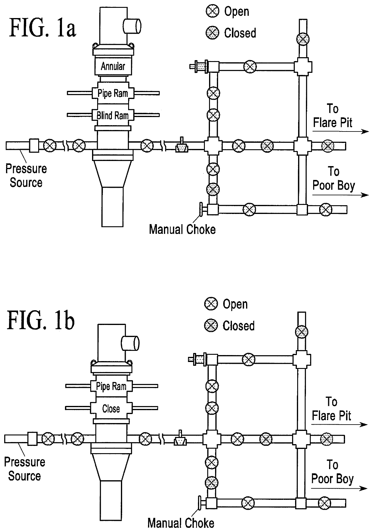
[0102]The regulation Part 250—Oil And Gas and Sulphur Operations in the Outer Continental Shelf Subpart D—Oil and Gas Drilling Operations; § 250.447-§ 250.451) require that the BOP systems in the United States (Title 30: Mineral Resources, on a drilling rig for both onshore and offshore rigs be pressure tested according to Part 250, Subpart D, Sections 250.447-250.45. The pressure test is designed to insure that all parts of the BOP are operationally functional, i.e., pipes and flanges do not leak and valves seal completely when closed so that there is no flow across the valve.

[0103]To test the BOP for integrity safely and / or in accordance with BOP regulations, a pressure testing system, or its alternative, a constant-pressure, volumetric testing system needs to be performed at two pressures. For safety and efficiency, a test should be performed at a lower pressure (e.g., between 200 and 300 psig) to verify that the system passes before raising the pressure to higher pressures (e.g....


PUM

PropertyMeasurementUnit
pressureaaaaaaaaaa
pressureaaaaaaaaaa
initial pressureaaaaaaaaaa

Abstract

A method and apparatuses for testing the blowout preventer (BOP) piping system on a drilling rig for leaks. The method and apparatuses can be used in conjunction with a pressure or volumetric method to more accurately test the BOP for integrity and to shorten the total time of testing.

Description

RELATED APPLICATIONS[0001]This application is a continuation of U.S. patent application Ser. No. 14 / 545,476 filed May 8, 2015, which claims the benefit of U.S. Provisional Patent Application Ser. No. 61 / 990,508 filed May 8, 2014, which both applications are incorporated by reference herein.BACKGROUND OF THE INVENTIONField of the Invention[0002]A method and apparatuses for testing the blowout preventer (BOP) piping system on a drilling rig for leaks. The method and apparatuses are comprised of a pressure, or alternatively a volumetric system, to test the piping and flanges for integrity and an acoustic sensor system to verify that the valves isolating the system for the integrity testing are completely sealed. The use of an acoustic valve sensing system with an integrity test minimizes the number of false alarms due to flow across an incompletely sealed valve and reduces the time to mitigate these false alarms.Brief Description of Prior Art[0003]Currently, regulations in the United S...

Claims


Application Information

Patent Timeline
Patent Type & Authority Patents(United States)
IPC IPC(8): E21B47/06G01M3/28E21B33/06E21B34/02E21B47/107E21B47/117
CPCE21B47/06E21B33/06E21B34/02E21B47/107E21B47/117G01M3/2876
Inventor MARESCA, JR., JOSEPH W.
Owner VISTA RES INC
Learn More