
Multi-section laser for fast modulation and broad spectral linewidth

a multi-section laser and broad spectral linewidth technology, applied in semiconductor lasers, planar/plate-like light guides, instruments, etc., can solve the problems of introducing fringe image artifacts, many challenges, and costs, and the process of immersing users into a mixed-reality environment creates many challenges, difficulties, and costs, so as to reduce the turn-on delay of laser diodes, reduce the turn-on time, and increase the spectral linewidth

Active Publication Date: 2021-03-09
MICROSOFT TECH LICENSING LLC
View PDF10 Cites 0 Cited by
  • Summary
  • Abstract
  • Description
  • Claims
  • Application Information

AI Technical Summary

Benefits of technology

The patent describes a system and method for controlling laser driver circuitry to reduce the time it takes for a laser to turn on and increase the spectral width of the light it generates. This is achieved by using a multi-section laser with pre-bias and gain sections, which are controlled using the laser driver circuitry. The pre-bias section is used to seed the laser with photons that reduce the delay and increase the spectral breadth of the resulting laser pulse. Once the laser is seeded, the gain current is applied to generate the desired optical intensity for a pixel. This system and method enable the multi-section laser to produce spectrally broad light with reduced delay.

Problems solved by technology

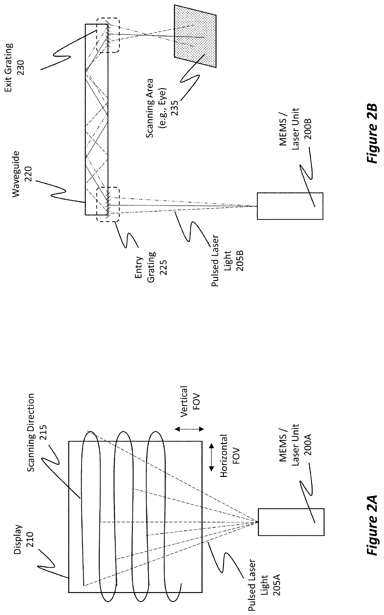
Notwithstanding these advances, the process of immersing a user into a mixed-reality environment creates many challenges, difficulties, and costs, particularly with regard to providing high-quality virtual images to the user.
Often, however, the narrow spectral linewidth of laser-based displays cause certain fringe image artifacts (e.g., Newton Rings) to be introduced into those virtual images due to forced attempts of using traditional lasers having suboptimal light coherence characteristics.
Such imperfections / image artifacts can negatively impact the display quality and the user's experience.

Method used


Image

  • Multi-section laser for fast modulation and broad spectral linewidth
  • Multi-section laser for fast modulation and broad spectral linewidth
  • Multi-section laser for fast modulation and broad spectral linewidth

Examples


Embodiment Construction

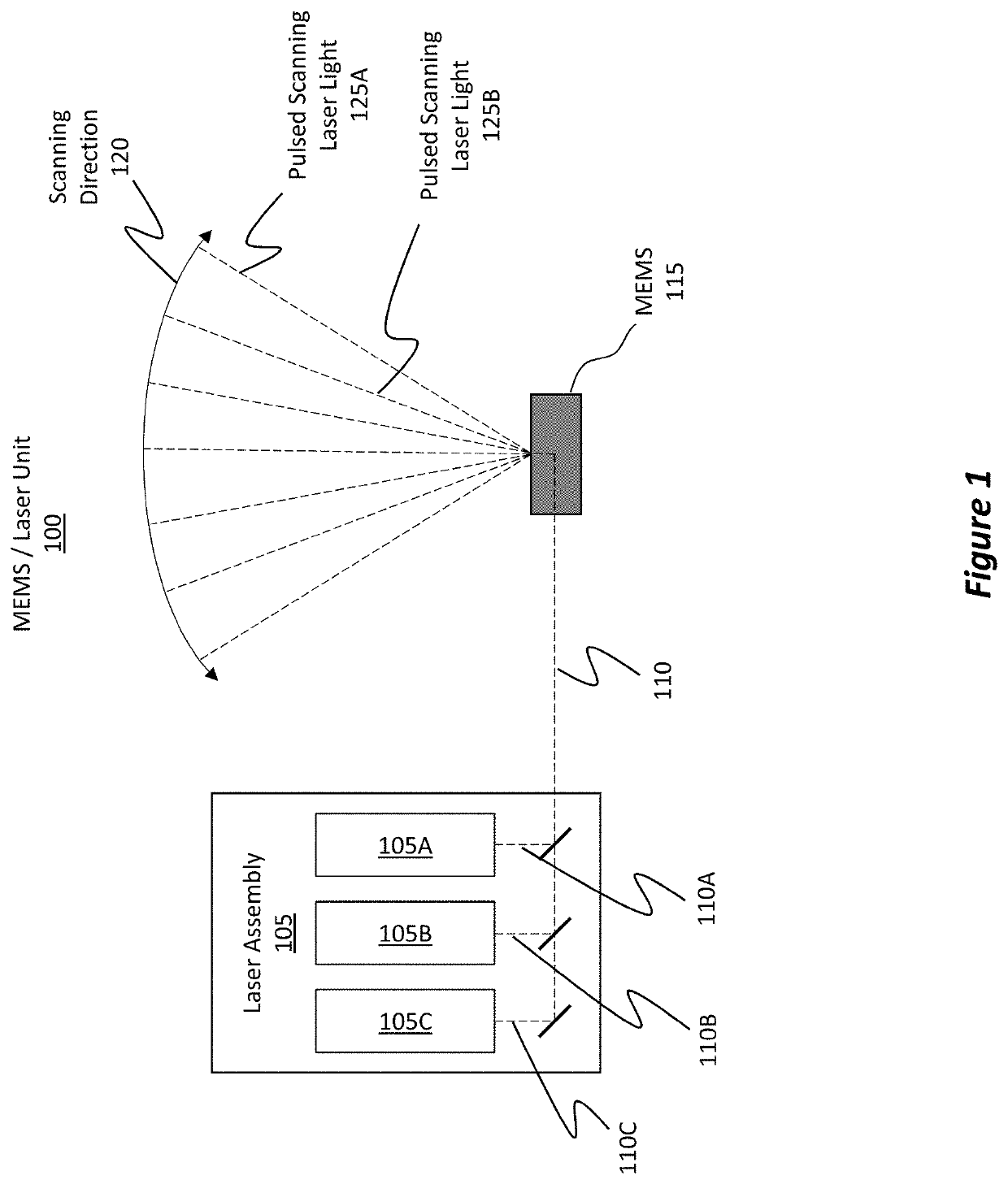
[0022]The disclosed embodiments include systems, methods, and devices that include multi-section lasers and control laser driver circuitry to reduce a turn-on delay associated with the multi-section lasers, and which, thereby, enable / configure the multi-section laser to generate laser light having a spectral linewidth that satisfies a threshold linewidth requirement.

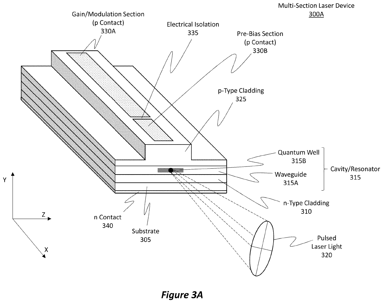
[0023]In some embodiments, a multi-section laser is specifically configured with a gain / modulation section and a pre-bias section, as well as laser driver circuitry for independently applying current to the different sections of the laser. Both of the laser sections are electrically connected to a diode laser resonator and are independently controllable via the laser driver circuitry. Initially, a minimum amount / threshold of pre-bias current is applied to the pre-bias section, thereby causing photons to be spontaneously emitted, where these photons' wavelengths span a broad range of wavelengths. During this time, the las...


PUM

PropertyMeasurementUnit
FWHMaaaaaaaaaa
FWHMaaaaaaaaaa
FWHMaaaaaaaaaa

Abstract

Multi-section laser systems are configured with a gain / modulation section and a pre-bias section. Both sections are electrically connected to a diode laser resonator and both sections are independently controllable via laser driver circuitry. The multi-section laser can be used to provide pulsing optimizations that include reducing the turn-on delay of the laser while also ensuring that the resulting laser light's spectral linewidth satisfies a threshold linewidth requirement. During use, a pre-bias current is applied to the pre-bias section. This current causes some photons to be spontaneously emitted. During this time, a gain current is refrained from being applied to the gain section until the resonator is seeded with a spectrum of photons from the pre-bias section. Once the resonator is sufficiently seeded, the gain current is applied to the gain section, thereby producing a seeded pulse of laser light having a desired spectral linewidth.

Description

BACKGROUND[0001]Mixed-reality systems, including virtual-reality (VR) and augmented-reality (AR) systems, have received significant attention because of their ability to create truly unique experiences for their users. For reference, conventional VR systems create a completely immersive experience by restricting their users' views to only virtual environments. This is often achieved through the use of a head-mounted device (HMD) that completely blocks any view of the real world. As a result, a user is entirely immersed within the virtual environment. In contrast, conventional AR systems create an augmented-reality experience by visually presenting virtual images (i.e. “holograms”) that are placed in or that interact with the real world.[0002]As used herein, VR and AR systems are described and referenced interchangeably. Unless stated otherwise, the descriptions herein apply equally to all types of mixed-reality systems, which (as detailed above) include AR systems, VR systems, and / o...

Claims


Application Information

Patent Timeline
Patent Type & Authority Patents(United States)
IPC IPC(8): G02B26/08H01S5/068G02B26/10G02B27/01H01S5/042H01S5/0625H01S5/40F21V8/00H01S5/026H01S5/22H01S5/34
CPCH01S5/06812G02B26/0833G02B26/105G02B27/0172H01S5/0425H01S5/0625H01S5/4093G02B6/005G02B6/0026G02B2027/012G02B2027/0112H01S5/026H01S5/22H01S5/34H01S5/041
Inventor PRICE, RAYMOND KIRKREIDY, CHRISTOPHER FRANCISZANG, KAI
Owner MICROSOFT TECH LICENSING LLC
Learn More