Carrier element for introducing a dry substance into a flow cell

a technology of flow cell and carrier element, which is applied in the direction of analytical using chemical indicators, laboratory glassware, instruments, etc., can solve the problems of occupying a large space in the drying chamber, and affecting the flow cell component itself, so as to achieve the effect of easy production

Active Publication Date: 2021-03-16
THINXXS MICROTECHNOLOGY AG
View PDF31 Cites 1 Cited by
  • Summary
  • Abstract
  • Description
  • Claims
  • Application Information

AI Technical Summary

Benefits of technology

[0004]The invention is based on the goal of creating a new microfluidic flow cell of the type described above with an integrated dry substance, which cell can be produced more easily than the prior art allows without the assembly environment causing any impairment to the dry substance or to any other of the components of the flow cell.
[0006]It is advantageous for the dry substance to be obtained by drying a reagent liquid on a carrier element separate from the entire rest of the flow cell, this carrier element serving solely to hold the dry substance, which thus makes it possible to introduce the dry substance into the flow cell in a subsequent assembly step. The risk of impairment to the components of the flow cell by the drying process and the risk of impairment to the introduced dry reagent by additional assembly work on the flow cell are eliminated. The carrier element can be much smaller than the flow cell, wherein the dimensions of the carrier element are oriented around the size of the area intended to carry the dry reagent. Coatings which promote the adhesion of the dry substance to its carrier surface can advantageously remain limited to the carrier surface of the carrier element, so that such coatings cannot, negatively affect the welds or adhesive bonds.
[0013]The carrier element preferably comprises a section which projects outwardly from the flow cell, which section can serve as a gripping part for facilitating manual handling or automated assembly.
[0018]The carrier element and the carrier surface carrying the dry reagent consist preferably of plastic. Alternatively, the carrier surface can be made of a separate surface component of glass, silicon, ceramic, or metal, which is connected to the rest of the carrier element and which is applied by means of welding or adhesive bonding. This is advantageous when the surface required for the application of the dry reagent cannot be realized by means of a plastic surface or a coating.

Problems solved by technology

The disadvantage is that the component, the dimensions of which usually far exceed those of the area to be dried, takes up a great deal of space in a drying chamber.
In addition, the drying treatment can impair this flow cell component itself, especially the sensitive components mounted on it.

Method used


Image

  • Carrier element for introducing a dry substance into a flow cell
  • Carrier element for introducing a dry substance into a flow cell
  • Carrier element for introducing a dry substance into a flow cell

Examples


Embodiment Construction

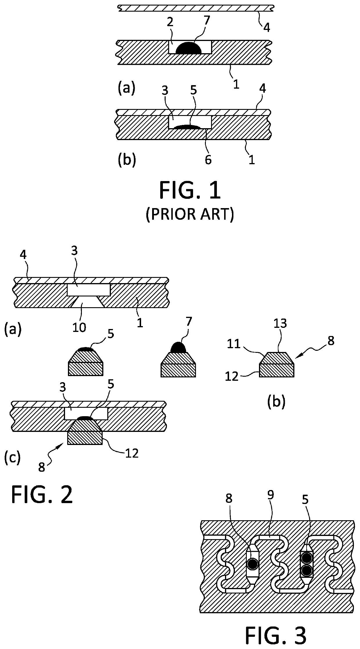
[0029]A flow cell, part of which is shown in FIG. 1, comprises a plate-shaped substrate 1 with a recess 2, which is covered to form a cavity 3 by a film 4, which is adhesively bonded and / or welded to the substrate. The cavity 3 is part of a channel network of the flow cell (the rest of which not being shown in FIG. 1); in particular, it forms a channel area in which a dry reagent 5 comprising antibodies, for example, adheres to a channel wall 6.

[0030]The dry reagent 5 originates from a reagent liquid 7, which is dispensed into the recess 2 forming a channel or chamber area of the flow cell before the recess 2 is sealed by the film 4. To obtain the dry reagent 5 from the reagent liquid 7, the entire substrate 1 is subjected to a heat treatment and / or a freeze-drying process.

[0031]FIG. 2 shows a method for introducing a dry substance, especially a dry reagent 5, into a flow cell, in which the dry reagent 5 is applied to a separate carrier part 8. A cavity 3 in a flow cell, which can b...


PUM

PropertyMeasurementUnit
thicknessaaaaaaaaaa
thicknessesaaaaaaaaaa

Abstract

A carrier element for introducing a dry substance into a cavity of a microfluidic flow cell or a chamber or cavities for interacting with a fluid, including: a plug-like body figure to be insertable into a passage of the flow cell leading to the cavity; and, a carder surface for receiving the drive substance, the carder surface being at an end of the body facing the cavity when the body is inserted in the passage.

Description

CROSS-REFERENCE TO RELATED APPLICATIONS[0001]The present application is a Continuation-In-Part Application of U.S. patent application Ser. No. 14 / 902,787, filed Jan. 4, 2016, which is a 371 of International application PCT / EP2014 / 064290, filed Jul. 4, 2014, which claims priority of EP 13 175 335.2, filed Jul. 5, 2013, the priority of these applications is hereby claimed and these applications are incorporated herein by reference.BACKGROUND OF THE INVENTION[0002]The invention pertains to a microfluidic flow cell with a dry substance arranged in a cavity inside the flow cell for interaction with a fluid present in the cavity.[0003]Microfluidic flow cells, which are being used increasingly as “minilabs” for the analysis and / or synthesis of fluids, especially in the field of diagnostics, contain reactive substances in liquid and / or solid form, which are introduced into the flow cells during the production of the cells. To introduce a dry reagent, one of the assembly steps involves apply...

Claims


Application Information

Patent Timeline
Patent Type & Authority Patents(United States)
IPC IPC(8): B01L3/00G01N35/00G01N33/48G01N15/06G01N33/00G01N31/22G01N33/52
CPCB01L3/502715B01L3/52B01L2200/0689B01L2200/16B01L2300/042B01L2300/0816B01L2300/0848B01L2300/12B01L2300/123
Inventor WEBER, LUTZRÖSER, TINA
Owner THINXXS MICROTECHNOLOGY AG
Why Eureka
Try Eureka