Method of limiting permeability of a matrix to limit liquid and/or gas inflow

a technology of permeability and matrix, applied in the direction of drilling composition, chemistry apparatus and processes, foundation engineering, etc., can solve the problems of preventing or reducing, hydrofracturing if applied to an unconsolidated matrix, and leaving sections of unconsolidated matrix on either side of the created seams

Active Publication Date: 2021-03-16
RELBORGN +1
View PDF32 Cites 1 Cited by
  • Summary
  • Abstract
  • Description
  • Claims
  • Application Information

AI Technical Summary

Benefits of technology

[0013]According to a first aspect of the present invention there is provided a method of limiting or reducing liquid and / or gas inflow through a permeable matrix, such as a geological formation, comprising measuring one or more parameters relating to said matrix and selecting one or more components of a multi-component sealing composition based on a polymer emulsion or colloid with reference to said measured parameters and introducing said components of said sealing composition into said permeable matrix where it is set or coagulated in a non-exothermic or low exothermic setting process to form a seal barrier. The method is particularly suited to limiting or reducing liquid inflow through a matrix. Such liquids may for example include water, oil, solvents and other chemicals. The method may also be used to prevent gas inflow through a matrix or to confine gas to a particular reservoir.
[0014]Low or non-exothermic setting has potential benefits such as avoidance of premature setting, lower shrinkage and lower mechanical stresses in comparison to exothermic setting systems, for example as encountered with epoxy resins and some polyurethane formulations. In addition, a concern with exothermic setting processes that cause non-linear polymer mass temperature increase and potential non-uniform curing can be addressed. The result is a seal barrier with more reliable barrier qualities.

Problems solved by technology

Sealing composition which is generally premixed prior to delivery of the site often provides less than satisfactory results in terms of preventing or reducing water inflow.
For example, injection or introduction of a cement based grout, known to have suitable properties in sealing passages, can cause hydrofracturing if applied to an unconsolidated matrix such as sand or sandstone.
This can create seams of grout within the matrix, leaving sections of unconsolidated matrix on either side of the created seams.
There is also difficulty in use of premixed grouts in that setting time cannot be controlled or varied either at all or with any reliable degree of accuracy.
This is detrimental in that known premixed grouts are generally capable only of providing a “one size fits all” sealing solution.
Since there is such a wide range of conditions that can be experienced when seeking to limit permeability of a matrix so as to limit liquid inflow, a ‘one size’ approach to all types of inflow problems is inherently unsuitable.
Traditional and pre-mixed cement and bitumen based grouts can additionally fail to adequately penetrate the passage or passages to be sealed.
At least part of this failure can be attributed to the sealing composition simply failing to penetrate through the matrix to a required depth, for example where passages are of small dimension.
Rate of setting of the sealing composition can also affect whether or not the sealing composition is able to adequately prevent or practically reduce water inflow.
If setting occurs prematurely, the grout is unable to adequately penetrate the matrix and create sufficient adhesion of particles in the matrix to form an effective seal to water inflow.
Further, set time of the grout cannot be regulated or varied with any degree of reliability to accommodate, for example, specific needs or requirements of the application at hand.
Proper execution of this method, particularly at depth, is complex and requires substantial capital outlay.
If it is not water tight, seepage can dissolve matrix from behind the shaft lining, increasing the leakage path and ultimately flooding the mine.
Salt mines in particular are known to be susceptible to this due to the salt dissolving and mines have been lost in this manner.
Known methodologies for reducing permeability of the ground to prevent or limit this have thus far been found to be largely ineffective or unreliable.

Method used


Image

  • Method of limiting permeability of a matrix to limit liquid and/or gas inflow
  • Method of limiting permeability of a matrix to limit liquid and/or gas inflow
  • Method of limiting permeability of a matrix to limit liquid and/or gas inflow

Examples


Embodiment Construction

[0042]The present invention may be better understood from the following description of preferred embodiments and examples and with reference to the accompanying drawings, in which:

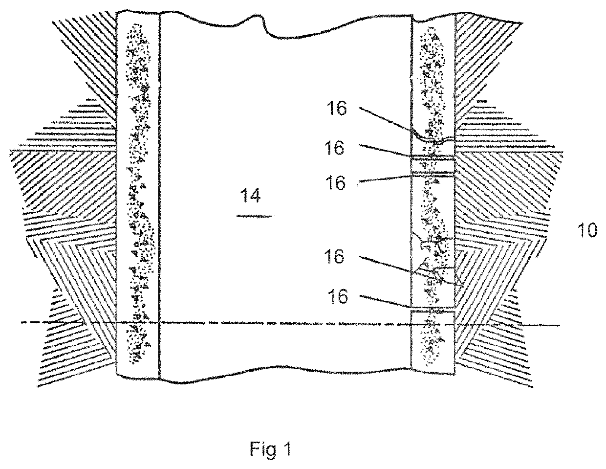
[0043]FIG. 1 is a cross-sectional view of a geological body, containing a shaft having cracks or apertures in the matrix surrounding the shaft that requires sealing to prevent or minimise water inflow into the shaft;

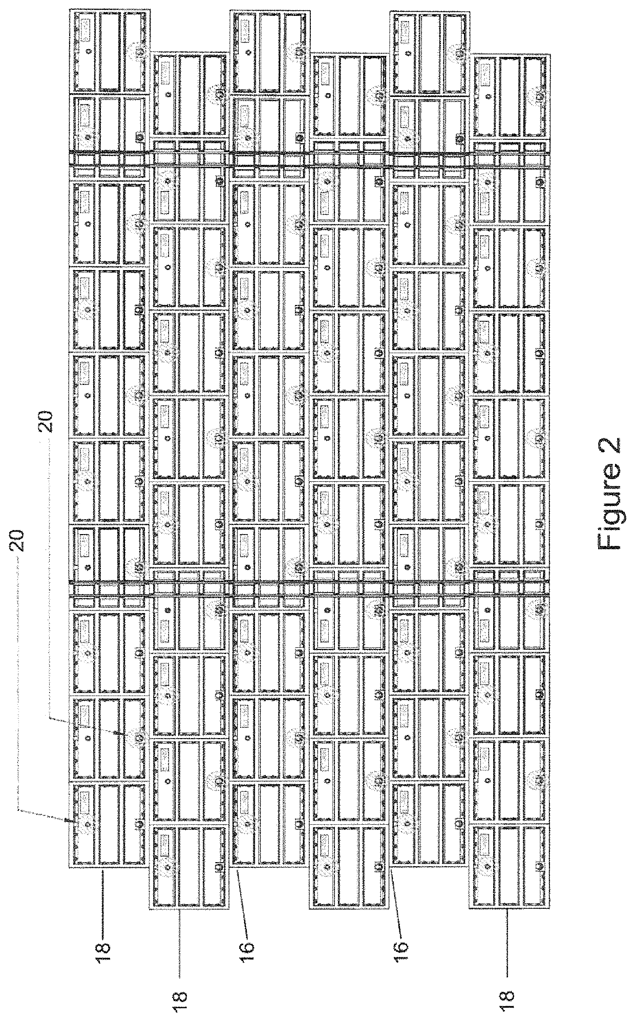
[0044]FIG. 2 is a front view of a section of a series of tubbing rings lining a shaft sunk into a matrix requiring treatment to limit water inflow into the shaft;

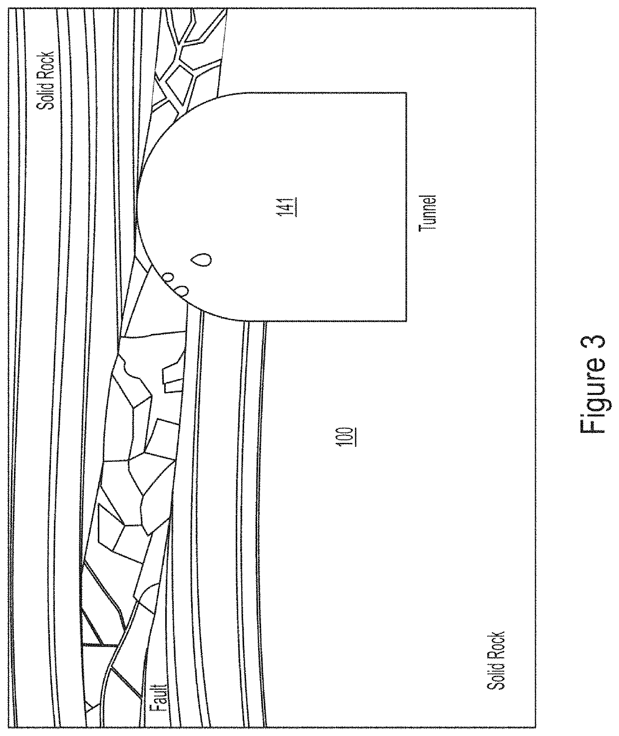
[0045]FIG. 3 is a cross-sectional view of a geological body with a mine shaft excavated therein and requiring treatment to limit water inflow, prior to any treatment;

[0046]FIG. 4 is a cross-sectional view of the geological body of FIG. 3 being treated to limit water inflow into the mine shaft in accordance with the present invention;

[0047]FIG. 5 is a cross-sectional view of the geological body of FIG. 3, wherein a first further additiv...


PUM

PropertyMeasurementUnit
particle sizeaaaaaaaaaa

Abstract

A method of limiting or reducing permeability of a matrix to liquid and / or gas inflow is described. The method includes limiting inflow of water, liquid and / or gas into passages such as cavities, fissures, voids and the like, encountered in formations such as geological formations though can be used to form barriers to water, liquid or gas flow through a matrix. The method includes steps of measuring one or more parameters relating to the matrix and selecting one or more components of a multi-component sealing composition with reference to the measured parameters. The selected components are introduced into the matrix where it is set or coagulated in a non-exothermic or low exothermic process to form a seal barrier. Also disclosed is a sealing composition comprising a coagulable polymer emulsion or colloid contactable with at least one selected additive which interacts with the polymer emulsion or colloid to form a coagulated mass for forming a sealing barrier in a non-exothermic or low exothermic setting process in which the polymer emulsion or colloid contains, prior to purposeful coagulation due to interaction with the selected additive, particles having a size distribution smaller than for Portland cement.

Description

CROSS REFERENCE TO RELATED APPLICATIONS[0001]This is a non-provisional patent application that claims priority to both Australian Provisional Patent Application No. 2017902673, filed Jul. 7, 2017, and Australian Innovation Patent Application No. 2017100604, filed on May 24, 2017 both of which are herewith incorporated by reference in their entireties.FIELD OF THE INVENTION[0002]The present invention relates to a method of limiting or reducing permeability of a matrix to liquid and / or gas inflow, including limiting inflow into passages such as cavities, fissures, voids, open features and pore spaces encountered in formations such as geological formations. The method may also be applied to sealing of passages in other situations such as construction, for example in tunnels, or forming sealing barriers to prevent fluid flow in other situations. The method may also be used to form barriers to liquid or gas flow within a permeable matrix.BACKGROUND TO THE INVENTION[0003]Methods of attemp...

Claims


Application Information

Patent Timeline
Patent Type & Authority Patents(United States)
IPC IPC(8): C09K8/44C04B40/00C09K8/46C09K8/508E02D3/12E02D31/14
CPCC09K8/44C04B40/0032C09K8/46C09K8/508E02D3/12E02D31/14C04B7/527C04B28/02
Inventor VAN DYK, DEONGROBLER, NICO JOHAN
Owner RELBORGN
Why Eureka
Try Eureka