Gas appliance and control method thereof
a technology of gas appliances and control methods, applied in the direction of domestic stoves or ranges, fuel supply regulation, combustion regulation, etc., can solve the problems of difficult user experience, long time requirements, and the decrease of the detected voltage much slower, so as to achieve less detection time
- Summary
- Abstract
- Description
- Claims
- Application Information
AI Technical Summary
Benefits of technology
Problems solved by technology
Method used
Image
Examples
first embodiment
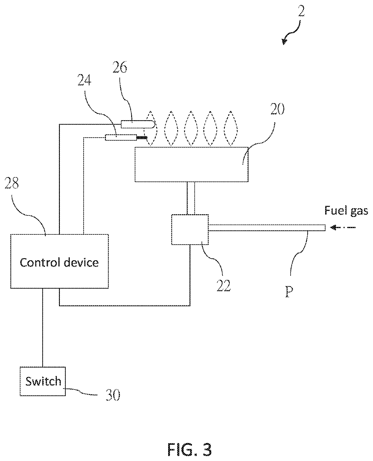
[0022]The following illustrative embodiments and drawings are provided to illustrate the disclosure of the present disclosure, these and other advantages and effects can be clearly understood by persons skilled in the art after reading the disclosure of this specification. As shown in FIG. 3, a gas appliance 2 of a first embodiment according to the present disclosure includes a burner 20, a gas valve 22, an igniter 24, a thermocouple 26, and a control device 28. In the present embodiment, the gas appliance 2 is a gas stove as an example, though it is not limited thereto. The gas appliance 2 may be a gas heating device such as a fireplace or a water heater, etc.
[0023]The burner 20 includes at least one flame port and is adapted to burn fuel gas to generate a flame. The gas valve 22 is installed on a gas pipe P communicating with the burner 20. The gas valve 22 is controlled to open or close the gas pipe P for regulating the fuel gas flowing into the burner 20. The igniter 24 is adjac...
second embodiment
[0032]Once the control device 28 receives the detected voltage below the second voltage value V2 even if which is temporary, the control device 28 still defines that the flame is extinguished and then controls the gas valve 22 to close the gas pipe P. For example, the flame does not contact with the thermocouple 26 briefly due to being blown by the wind, but soon contacts with the thermocouple 26 again, which means that the detected voltage generated by the thermocouple 26 may fall below the second voltage value V2 briefly and rise above the second voltage value V2 again. The aforementioned situation is defined to be a misjudging extinguishment. Thus, in order to avoid the misjudging extinguishment, in a second embodiment, the following step is further included. The control device 28 controls the gas valve 22 to close the gas pipe P when the detected voltage has been below the second voltage value V2 for a first predetermined period of time. As such, the gas pipe P may not be closed...
third embodiment
[0033]In a third embodiment, the following steps may be further included for controlling the gas appliance 2. The control device 28 is adapted to detect the fuel gas flowing in the burner 20 which is regulated by the gas valve 22 (e.g., the fuel gas flow is detected based on an opening degree of the gas valve 22 or is measured by an anemometer). When the fuel gas flow has reached a predetermined fuel gas flow for a second predetermined period of time (e.g., two to five minutes in the present embodiment), or when a slope derived from the detected voltage with respect to the detection period of time is decreased to a predetermined slope value (which means that the flame is in a stable temperature), at this time, the detected voltage is recorded as a recorded voltage value and then the first voltage value V1 for a next ignition procedure is renewed according to the recorded voltage value. The predetermined slope value is greater than or equals to zero. In the present embodiment, the re...
PUM
 Abstract
Description
Claims
Application Information
 - R&D
- Intellectual Property
- Life Sciences
- Materials
- Tech Scout
- Unparalleled Data Quality
- Higher Quality Content
- 60% Fewer Hallucinations
Browse by: Latest US Patents, China's latest patents, Technical Efficacy Thesaurus, Application Domain, Technology Topic, Popular Technical Reports.
© 2025 PatSnap. All rights reserved.Legal|Privacy policy|Modern Slavery Act Transparency Statement|Sitemap|About US| Contact US: help@patsnap.com


