Method for determining the state of wear of a drill, and corresponding device

a drill and wear state technology, applied in the direction of instrumentation, programme control, measurement/indication equipment, etc., can solve the problems of drill bit wear, drill bit performance impact, drilling operation that does not comply,

Active Publication Date: 2021-03-23
SETI TEC
View PDF12 Cites 3 Cited by
  • Summary
  • Abstract
  • Description
  • Claims
  • Application Information

AI Technical Summary

Benefits of technology

[0091]This makes it possible to provide a warning that the drill bit is no longer capable of carrying out a drilling operation that meets with the requisite criteria of quality. An operator could thus easily know the right time at which to replace a drill bit so as to use it for as long as it is still usable and to replace it only when it is no longer usable. The invention thus averts the deterioration of the quality of the drilling operations performed.
[0100]Such a preliminary laboratory assessment enables an efficient determination of the borderline thresholds of each state of wear.
[0116]This implementation makes it possible to carry out an efficient weighting according to the abrasiveness of the materials.
[0140]It is thus possible to determine states of wear closer to reality by taking account of the abrasiveness of the materials drilled in the context of taking account of the number of entries into the material by a drill bit.

Problems solved by technology

This drill bit therefore tends to get worn out in the course of the drilling operations.
The wear of the drill bits has an impact on the quality of the drilling operations performed when they are implemented.
Hence, the state of wear of the drill bits must be monitored in order to:prevent a worn-out drill bit from being used to carry out drilling operations: this leads to the performance of drilling operations that do not comply with the requisite quality criteria;prevent the premature replacement of a drill that is not yet worn out and could still be used to create quality bores: this leads to excessive consumption of drill bits and major tooling costs.
This type of monitoring is not optimal.
Indeed, the structures to be drilled during production are complicated.
As a result, it is impossible to have precise knowledge, at each drilling operation during production, of the exact nature, in terms of materials and thicknesses of layers, of the structure being drilled.
This complexity makes it impossible to carry out trials for qualifying a drill bit by carrying out laboratory drilling of samples that are identical, in terms of materials and thicknesses of layers, to the structures that will be drilled in production.
This leads to replacing the drill bits prematurely since not all the drilling operations carried out in production are the most unfavorable cases.
This type of monitoring too is not optimal because it especially does not consider the following:the nature of the material or materials drilled and especially their abrasive effect;the depth drilled;the cutting speeds and feedrates;the implementing or non-implementing of lubrication;etc.
However, the wear capacity that each of the materials exerts on the drill bits is different.
The drilling of a titanium element can therefore cause the tip of the drill bit used for this purpose to get chipped.
The drilling of a hole with a drill bit having a damaged tip causes poor centering of the drill bit and can therefore lead to the creation of a poor-quality hole that does not comply with the requisite dimensional and geometrical tolerance values.
Carbon fiber is abrasive and tends to blunt the effect of the cutting lips of the drill bits.
Aluminum alloys can give rise to chips that adhere to the drill bit and / or wear out the coating of the drill bit.
Hence, making the replacement of drill bits conditional on the number of cycles during which it has been used and on the most difficult conditions of use, without taking account properly speaking of the wear capacity of the materials actually being drilled during these drilling cycles, does not provide for optimized management of the replacement of the drill bits.
In addition, it can also happen that, inadvertently, drilling cycles are launched in untimely ways and are stopped even before the drill starts the corresponding drilling operation.
The use of a cycle counter in this case would lead to the counting of the untimely cycles and thus to the premature replacement of the drill bits.
Taking account of the stresses exerted on a drill bit during a drilling operation is not enough to accurately assess the stresses on the drills and to deduce their level of wear from this.

Method used


Image

  • Method for determining the state of wear of a drill, and corresponding device
  • Method for determining the state of wear of a drill, and corresponding device
  • Method for determining the state of wear of a drill, and corresponding device

Examples


Embodiment Construction

[0214]6.1. Device

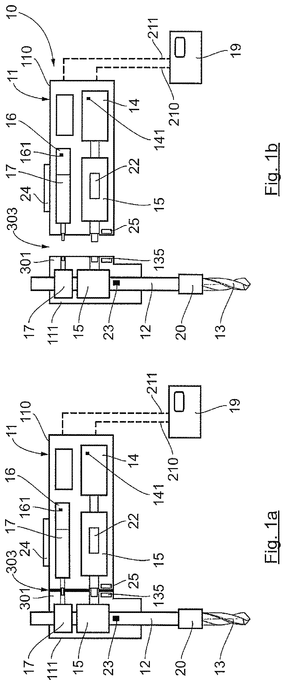
[0215]A drilling device or drill to implement a method according to the invention comprises a drill or a drilling robot with controlled cutting parameters. Such a drilling device is known per se to those skilled in the art and is not described in detail herein apart from the elements more specific to the invention.

[0216]As can be seen in FIGS. 1a and 1b, such a drilling device 10 comprises a casing 11.

[0217]The casing 11 comprises a first casing portion 110 and a second casing portion 111 that extend appreciably perpendicularly to one another. In one variant, the casing could extend along a single axis and thus not have an essentially T shape.

[0218]The drill comprises an output shaft 12 that is mobile in rotation and in translation along a same axis. This output shaft 12 is connected by means of one or more transmission chains to driving means.

[0219]In this embodiment, the driving means comprises:[0220]An electric rotational drive means 14 linked to the output shaft...


PUM


Abstract

A method is provided for assessing wear of a drill bit throughout its use for carrying out the drilling of elements to be drilled constituted by at least one layer and at least one material. The wear of the drill bit expresses its capacity to perform a drilling that meets at least one criterion of quality of a drilling. The method includes at least: measuring or detecting at least one parameter having an effect on the wear of the drill bit, the parameter being chosen from: the depth of drilling performed by the drill bit, and the entry of the drill bit into the element to be drilled; and determining at least one state of wear of the drill bit, each state of wear being determined as a function of one of the parameters and being characteristic of one of the criteria of quality of a drilling.

Description

1. CROSS-REFERENCE TO RELATED APPLICATIONS[0001]This Application is a Section 371 National Stage Application of International Application No. PCT / EP2017 / 050900, filed Jan. 17, 2017, the content of which is incorporated herein by reference in its entirety, and published as WO 2017 / 125392 on Jul. 27, 2017, not in English.2. FIELD OF THE INVENTION[0002]The field of the invention is that of techniques for the drilling of elements to be drilled and that of controlling or checking wear in cutting tools implemented for this purpose.[0003]The invention especially relates to methods and devices for controlling or checking the wear of drill bits.3. PRIOR ART[0004]Various drilling devices are commonly used in industry, for example in the aeronautics industry, to drill elements to be drilled.[0005]These devices conventionally include an output shaft to which there is detachably attached a cutting tool such as a drill. These drilling devices include especially:[0006]Hand-held drills, during the ...

Claims


Application Information

Patent Timeline
Patent Type & Authority Patents(United States)
IPC IPC(8): B23Q17/09B23B49/00G05B19/4065
CPCB23Q17/0995B23B49/001G05B19/4065G05B2219/37251G05B2219/37252G05B2219/37258
Inventor PEREIRA, SEBASTIEN
Owner SETI TEC
Why Eureka
Try Eureka