
Method for joining plated steel plates, and joined structure

a technology of plated steel and joint structure, which is applied in the direction of welding/cutting media/materials, manufacturing tools, welding apparatus, etc., can solve the problems of reducing the strength of welds in ultra-high-tensile steels, pore defects, and blowholes, so as to avoid deterioration of welding quality and variation in product dimensions, good joint structure

Pending Publication Date: 2022-04-14
KOBE STEEL LTD
View PDF6 Cites 0 Cited by
  • Summary
  • Abstract
  • Description
  • Claims
  • Application Information

AI Technical Summary

Benefits of technology

The present invention provides a method for joining plated steel sheets that results in a good joint structure without any pore defects. This is achieved by forming a gap that allows for the reliable discharge of gas generated during welding while ensuring welding quality and product dimensions remain consistent.

Problems solved by technology

In this case, when the steel sheets are in close contact with each other, there is no space for the zinc gas to escape, so the zinc gas enters the molten pool that is liquid iron, and pore defects called blowholes, pits, or pinholes occur.
Since pore defects reduce joining strength, pore defects are a major factor in reducing the strength of welds in ultra-high-tensile strength steels and are considered a problem.
However, the effectiveness in reducing pore defects, obtained by this technology, is limited, and further improvement is needed when applying it to ultra-high-tensile strength steels.
However, since laser welding is basically performed by penetration welding, it cannot be applied to fillet welding for edge portion, which is performed by arc welding, or even if it could be applied, the effect would be small.
As for the method of forming fine grooves by knurling in the above (B), it is difficult to form grooves in ultra-high-tensile strength steels by knurling, and the cost is very high.
In addition, heat input in arc welding is high, and as for the fine grooves such as those formed by knurling, the gap closes due to thermal deformation during the welding, making it difficult to smoothly discharge a large amount of zinc gas generated by the high heat input.
As for the method of causing strain deformation by laser in the above (C), if the main welding in the subsequent process is also laser welding, the same equipment can be used, which brings certain merits, but if the main welding is arc welding, a separate expensive investment in equipment is required, resulting in high costs.
In addition, a gap continued to a sheet edge portion or a large gap cannot be ensured by thermal deformation by laser heating, making it difficult to smoothly discharge a large amount of zinc gas.

Method used


Image

  • Method for joining plated steel plates, and joined structure
  • Method for joining plated steel plates, and joined structure
  • Method for joining plated steel plates, and joined structure

Examples


first embodiment

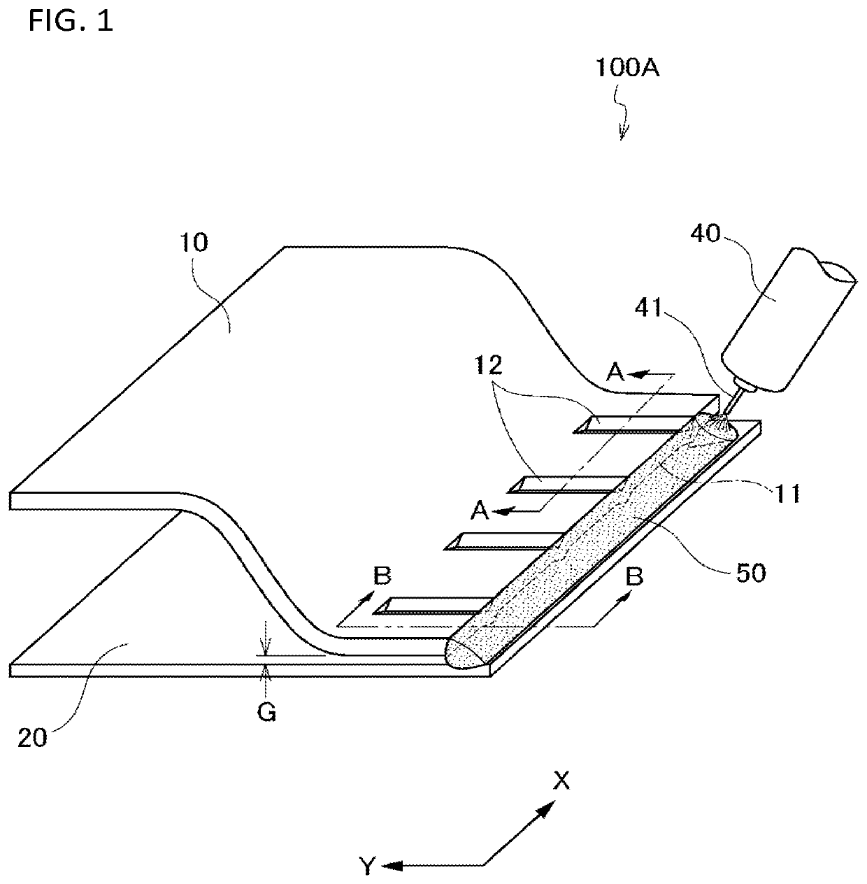
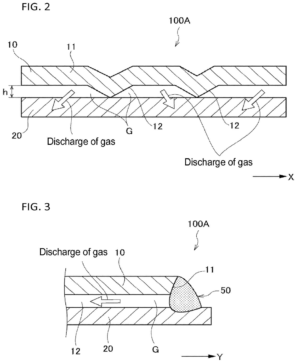
[0042]FIG. 1 is a perspective view schematically illustrating a method for joining a plated steel sheet in the first embodiment of the present invention. FIG. 2 is an A-A sectional view of FIG. 1, and FIG. 3 is a B-B sectional view of FIG. 1.

[0043]As illustrated in FIG. 1 to FIG. 3, a joint structure 100A is formed by arc welding (e.g. MAG welding) a first steel sheet 10 and a second steel sheet 20, which are overlapped with each other, linearly along an edge portion (i.e. side edge portion) 11 of the first steel sheet 10 by a welding torch 40. At least one of the first steel sheet 10 and the second steel sheet 20 is a galvanized steel sheet obtained by galvanizing. Examples of the galvanized steel sheet include a hot-dip galvannealed steel sheet (GA), a hot-dip galvanized steel sheet (GI), an electrogalvanized sheet steel (EG), and the like. The tensile strength (TS) of a galvanized steel sheet is not particularly limited, and for example, the galvanized steel sheet is a high tensi...

second embodiment

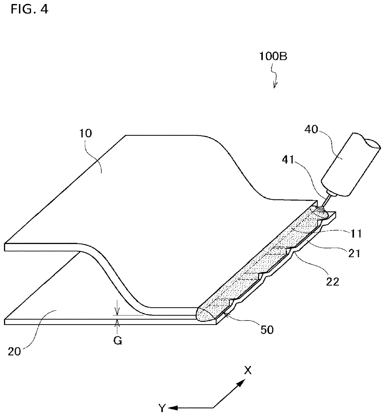
[0066]FIG. 4 is a perspective view schematically illustrating a method for joining a plated steel sheet in the second embodiment of the present invention.

[0067]In the joint structure 100B in this embodiment, a plurality of protrusions 22 that extends in a direction (Y-direction) substantially perpendicular to an edge portion 21 of the second steel sheet 20 and is positioned along the edge portion 21 (X-direction) is formed in the second steel sheet 20 overlapped with the first steel sheet 10. The protrusions 22 are formed in a substantially inverted V-shape that protrudes in a direction toward the overlapping surface of the first steel sheet 10 (upward in FIG. 4). The protrusions 12 are formed by press working the second steel sheet 20.

[0068]The joint structure 100B is formed by overlapping the first steel sheet 10 and the second steel sheet 20 in a state where the protrusions 22 of the second steel sheet 20 are in contact with the first steel sheet 10, and performing arc welding li...

third embodiment

[0072]FIG. 5 is a perspective view schematically illustrating a method for joining a plated steel sheet in the third embodiment of the present invention.

[0073]In the joint structure 100C in this embodiment, the first steel sheet 10 and the second steel sheet 20 are each formed in a substantially U-shape in cross section. The inner width W1 of the opening of the first steel sheet 10 is slightly larger than the outer width W2 of the opening of the second steel sheet 20, and the first steel sheet 10 and the second steel sheet 20 are assembled such that the respective openings face each other. Then, the first steel sheet 10 and the second steel sheet 20 are joined by performing arc welding along the edge portion 11 of the first steel sheet 10 to form a linear weld metal (weld bead) 50 in a weld.

[0074]A plurality of protrusions 12 that extends in a direction (Y direction) substantially perpendicular to the edge portion 11 of the first steel sheet 10 and is positioned along the edge porti...


PUM

PropertyMeasurementUnit
Heightaaaaaaaaaa
Heightaaaaaaaaaa
Tensile strengthaaaaaaaaaa

Abstract

A method for joining a plated steel sheet includes forming a plurality of protrusions, overlapping a first steel sheet, and performing arc welding, by which first and second steel sheets, at least one of which is a plated steel sheet, are arc welded. In the forming, the plurality of protrusions that is substantially perpendicular to an edge portion of the first steel sheet and is positioned along the edge portion is formed in an overlapping surface of the first steel sheet. In the overlapping, the first and second steel sheets are overlapped such that the protrusions protrude in a direction toward an overlapping surface of the second steel sheet. In the performing the arc welding, an arc welding is performed linearly in the edge portion of the first steel sheet or second steel sheet.

Description

TECHNICAL FIELD[0001]The present invention relates to a method for joining a plated steel sheet and a joint structure.BACKGROUND ART[0002]In a case where steel sheets, a surface of at least one of which has been galvanized for the purpose of corrosion protection (galvanized steel sheet), are overlapped and arc-welded linearly, when arc heat is applied to the overlapping surfaces of the steel sheets, the plated zinc may gasify when the temperature of the zinc exceeds its boiling point. In this case, when the steel sheets are in close contact with each other, there is no space for the zinc gas to escape, so the zinc gas enters the molten pool that is liquid iron, and pore defects called blowholes, pits, or pinholes occur. Since pore defects reduce joining strength, pore defects are a major factor in reducing the strength of welds in ultra-high-tensile strength steels and are considered a problem.[0003]There are two major common technologies for reducing pores during the welding of gal...

Claims


Application Information

Patent Timeline
IPC IPC(8): B23K9/025B23K9/167B23K9/12B23K35/38
CPCB23K9/025B23K9/167B23K2103/04B23K35/383B23K9/125B23K9/23B23K9/02B23K9/173B23K33/008B23K2101/34B23K9/235B23K9/073B21D22/20B21D24/04B23K9/16B23K9/124B23K2101/18
Inventor SUZUKI, REIICHI
Owner KOBE STEEL LTD
Learn More