Heat exchanger for an oxygenator and method for producing such a heat exchanger

a technology of heat exchanger and oxygenator, which is applied in the direction of heat exchanger casings, lighting and heating apparatus, stationary tubular conduit assemblies, etc., can solve the problems of polluting and/or damage of heat exchangers, and achieve the effect of simplifying the handling of bundles during insertion into the housing and simplifying the production of multiple bundles

Active Publication Date: 2021-03-23
RAUMEDIC AG
View PDF19 Cites 0 Cited by
  • Summary
  • Abstract
  • Description
  • Claims
  • Application Information

AI Technical Summary

Benefits of technology

[0006]It is an object of the present invention to improve a heat exchanger, in particular in such a way that the heat exchanger can be produced in an uncomplicated manner, and thus in particular the risk of pollution and / or damage during production is reduced.
[0008]The heat exchanger according to the invention has increased stability and rigidity. It is additionally stabilized, and in particular rigid, by the at least one connecting section comprising an adhesive. In particular a casting resin, and more particularly acrylate, phenolic resin, silicone, polyurethane or copolymer, can be used as the adhesive. It is also possible to use a thermoplastic casting compound as the adhesive. An acrylate can be cured by way of UV radiation, for example. However, it is also possible to achieve cross-linking using addition-crosslinking or radically crosslinking casting resins. A polycondensation reaction for cross-linking, or catalytic cross-linking, such as platinum-catalyzed silicone, is also possible. No cross-linking occurs with thermoplastic casting compounds, such as polyurethane.

Problems solved by technology

It is disadvantageous that a heat exchanger, in particular tube sections used therefor, can become polluted and / or damaged during production.

Method used


Image

  • Heat exchanger for an oxygenator and method for producing such a heat exchanger
  • Heat exchanger for an oxygenator and method for producing such a heat exchanger
  • Heat exchanger for an oxygenator and method for producing such a heat exchanger

Examples


Embodiment Construction

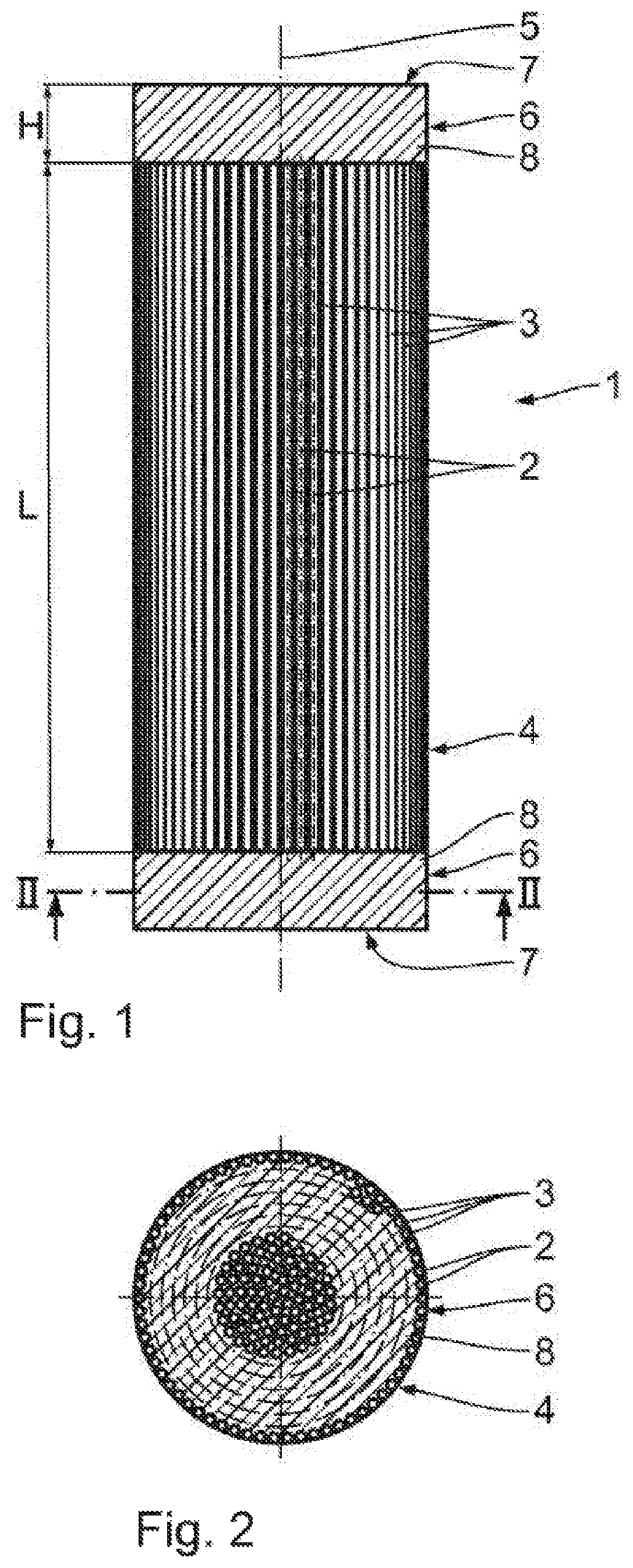
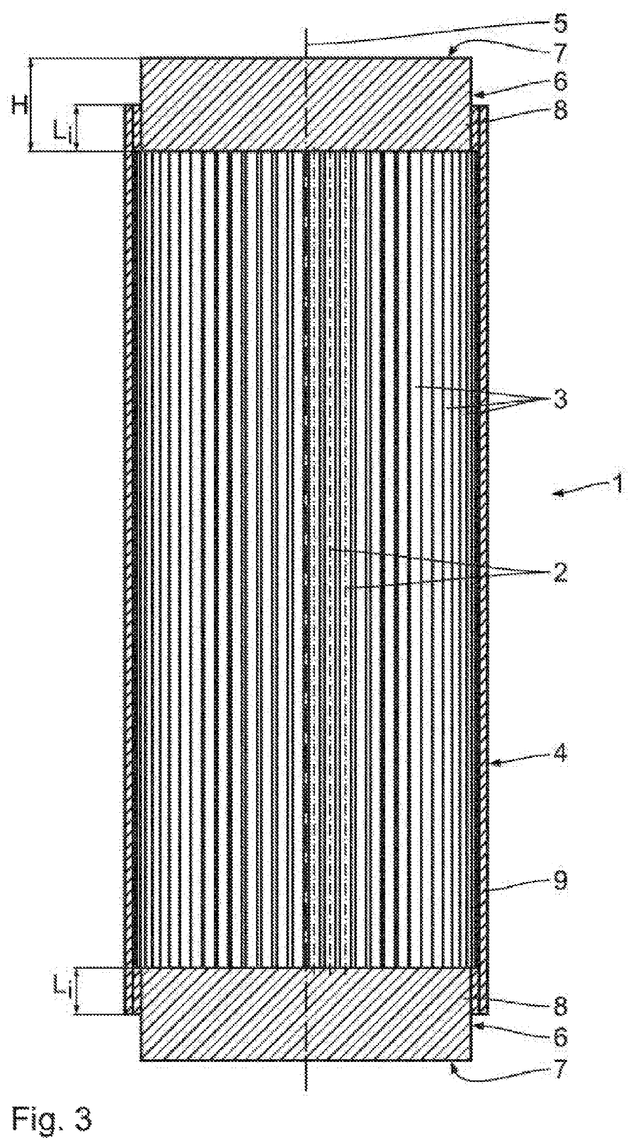
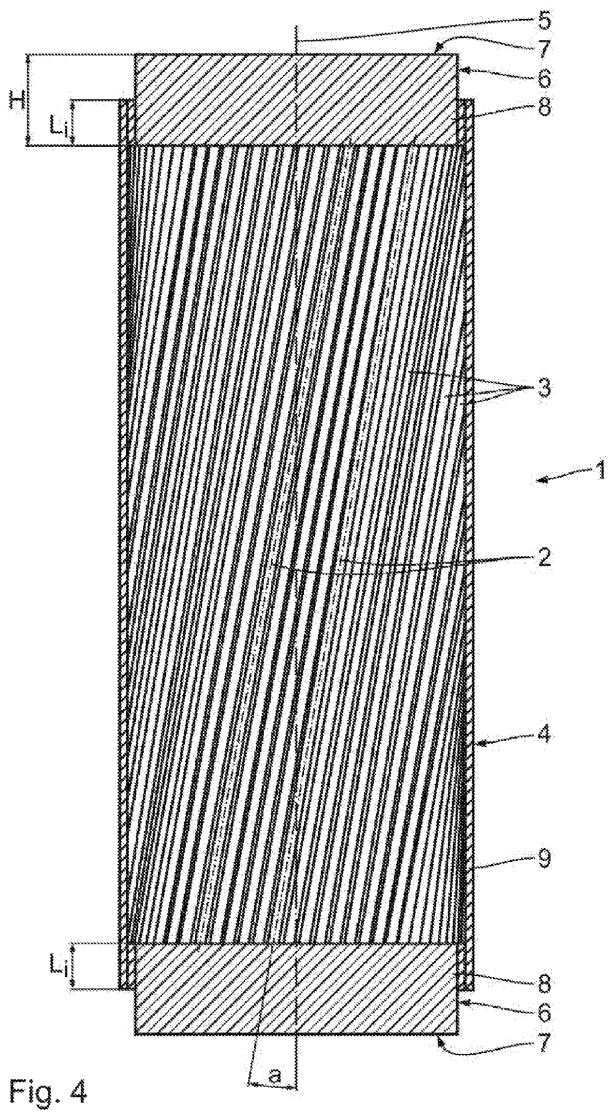
[0030]A heat exchanger 1 shown in FIGS. 1 to 3 comprises multiple tube sections 3, each having a longitudinal tube axis 2. The tube sections 3 are made of plastic material, and more particularly of polyurethane (PUR). Other plastic materials can also be used to produce the tube sections 3, such as polyester, in particular polyethylene terephthalate (PET) or polybutylene terephthalate (PBT), polyamides and co-polymers or polyurethanes and copolymers, in particular polyether polyurethane or polyester polyurethane.

[0031]According to the shown exemplary embodiment, the tube sections 3 are disposed to form a bundle 4, which has a longitudinal bundle axis 5. The tube sections 3 are disposed in each case in such a way that the longitudinal tube axes 2 thereof are in each case oriented parallel to each other and parallel to the longitudinal bundle axis 5.

[0032]The tube sections 3 are connected to each other in two two connecting sections 6, which are in each case disposed on bundle ends 7, ...


PUM


Abstract

A heat exchanger for an oxygenator comprises multiple tube sections, each having a longitudinal tube axis, wherein the tube sections are disposed as a bundle having a longitudinal bundle axis, and the tube sections are connected to each other in at least one connecting section of the bundle by joining by way of chemical and / or physical bonded joints. A method for producing the heat exchanger is also provided.

Description

CROSS-REFERENCE[0001]This application is a divisional of U.S. Non-Provisional patent application Ser. No. 14 / 387,129, filed Sep. 22, 2014, which is a U.S. national stage application of PCT Application Serial No. PCT / EP2013 / 053853, filed Feb. 27, 2013, which claims priority to German patent application DE 10 2012 204 705.0, filed Mar. 23, 2012, the entirety of each of which is hereby expressly incorporated herein by reference.FIELD OF THE INVENTION[0002]The invention relates to a heat exchanger for an oxygenator and to a method for producing such a heat exchanger.BACKGROUND OF THE INVENTION[0003]An oxygenator is an integral part of an extracorporeal blood circuit during open heart surgery. Temperature control takes place in a heat exchanger of the oxygenator by exchanging heat between the blood and a heat exchanger medium.[0004]A heat exchanger is known from DE 10 2010 000 820 A1, which comprises multiple tube sections that are knitted to each other by transversely extending knitted ...

Claims


Application Information

Patent Timeline
Patent Type & Authority Patents(United States)
IPC IPC(8): B21D53/06F28D7/10F28F9/16F28F21/06F28D7/16A61M1/16F28D21/00
CPCF28D7/103B21D53/06F28D7/16F28D7/1615F28D7/1669F28F9/162F28F21/06F28F21/062A61M1/1698F28D2021/005F28F2275/12Y10T29/49361A61M1/3623
Inventor STÖCKER, MARTINZEITLER, ANDREAS
Owner RAUMEDIC AG
Why Eureka
Try Eureka