Heat Exchanger for an Oxygenator and Method for Producing Such a Heat Exchanger

a technology of heat exchanger and oxygenator, which is applied in the direction of heat exchange apparatus, heat exchanger fastening, stationary tubular conduit assembly, etc., can solve the problems of polluting and/or damage of heat exchanger, and achieve the effect of simplifying the handling of bundles during insertion into the housing and simplifying the production of multiple bundles

Active Publication Date: 2018-08-09
RAUMEDIC AG
View PDF7 Cites 0 Cited by
  • Summary
  • Abstract
  • Description
  • Claims
  • Application Information

AI Technical Summary

Benefits of technology

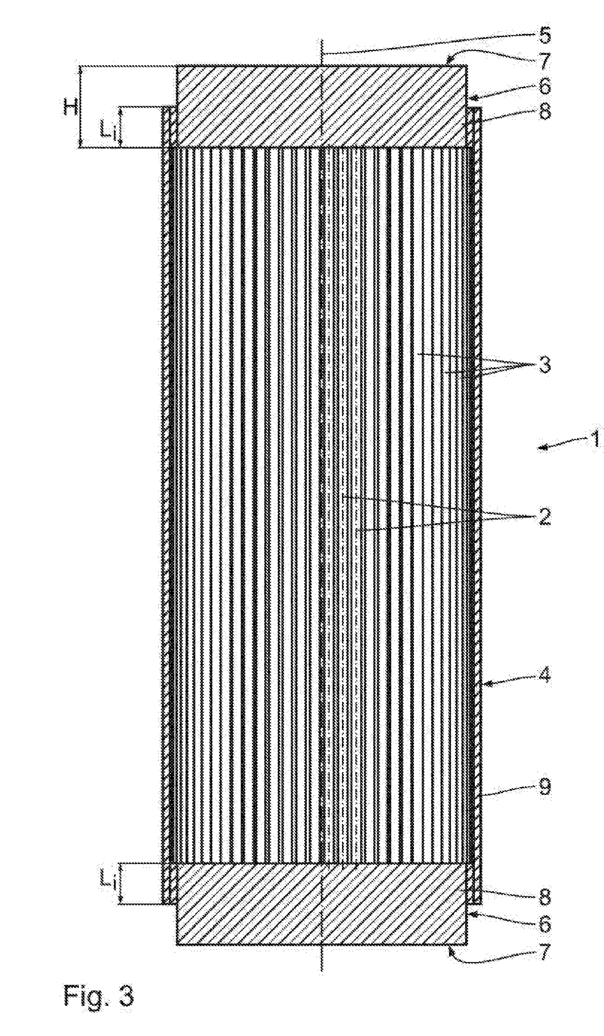
[0022]In a method according to claim 4, the bundle is inserted into the housing in such a way that in each case a connecting section disposed on a bundle end is disposed at least sectionally outside the housing. Handling of the bundle during insertion into the housing is thus simplified. In particular, it is possible to sever the regions of the connecting sections which protrude over the housing and thus create in particular a flush termination of the bundle on the housing.
[0023]A method according to claim 5 simplifies the production of multiple bundles. Such a method is especially suited in particular for mass production, since it is possible to produce multiple bundles simultaneously. For example, it is conceivable that tube sections having large lengths, which in particular correspond to multiple times a desired length of a heat exchanger, are disposed in bundle form, wherein the tube sections are connected to each other at a heat exchanger length. In particular, it is thus conceivable that tube sections are connected to each other at regular intervals in a connecting section, and subsequently such a “continuous” bundle is cut at the connecting sections, so that multiple bundles are available, having a connecting section disposed at the bundle ends in each case.

Problems solved by technology

It is disadvantageous that a heat exchanger, in particular tube sections used therefor, can become polluted and / or damaged during production.

Method used


Image

  • Heat Exchanger for an Oxygenator and Method for Producing Such a Heat Exchanger
  • Heat Exchanger for an Oxygenator and Method for Producing Such a Heat Exchanger
  • Heat Exchanger for an Oxygenator and Method for Producing Such a Heat Exchanger

Examples


Embodiment Construction

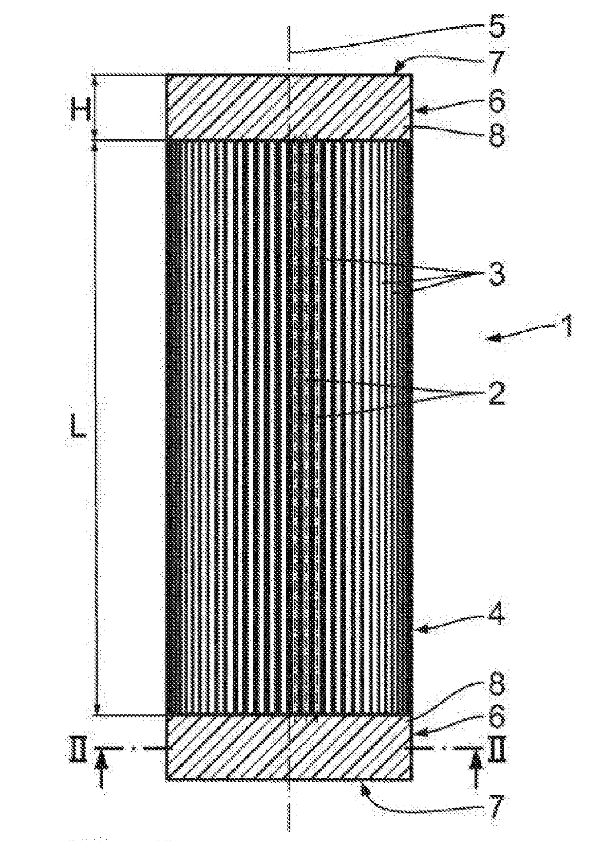
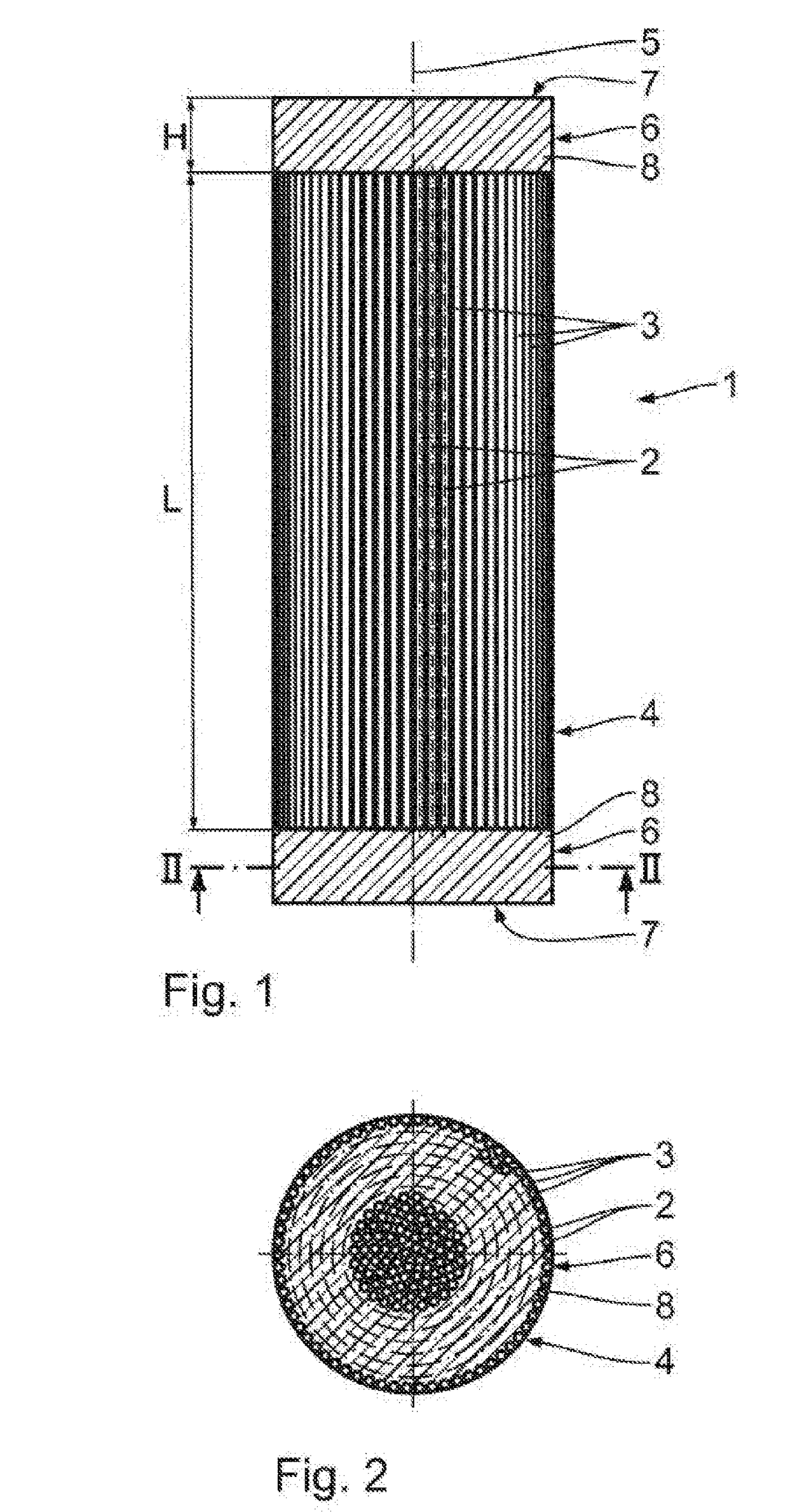
[0030]A heat exchanger 1 shown in FIGS. 1 to 3 comprises multiple tube sections 3, each having a longitudinal tube axis 2. The tube sections 3 are made of plastic material, and more particularly of polyurethane (PUR). Other plastic materials can also be used to produce the tube sections 3, such as polyester, in particular polyethylene terephthalate (PET) or polybutylene terephthalate (PBT), polyamides and co-polymers or polyurethanes and copolymers, in particular polyether polyurethane or polyester polyurethane.

[0031]According to the shown exemplary embodiment, the tube sections 3 are disposed to form a bundle 4, which has a longitudinal bundle axis 5. The tube sections 3 are disposed in each case in such a way that the longitudinal tube axes 2 thereof are in each case oriented parallel to each other and parallel to the longitudinal bundle axis 5.

[0032]The tube sections 3 are connected to each other in two two connecting sections 6, which are in each case disposed on bundle ends 7, ...


PUM

PropertyMeasurementUnit
angleaaaaaaaaaa
angleaaaaaaaaaa
angleaaaaaaaaaa

Abstract

A heat exchanger for an oxygenator comprises multiple tube sections, each having a longitudinal tube axis, wherein the tube sections are disposed as a bundle having a longitudinal bundle axis, and the tube sections are connected to each other in at least one connecting section of the bundle by joining by way of chemical and/or physical bonded joints. A method for producing the heat exchanger is also provided.

Description

CROSS-REFERENCE[0001]This application is a divisional of U.S. Non-Provisional patent application Ser. No. 14 / 387,129, filed Sep. 22, 2014, which is a U.S. national stage application of PCT Application Serial No. PCT / EP2013 / 053853, filed Feb. 27, 2013, which claims priority to German patent application DE 10 2012 204 705.0, filed Mar. 23, 2012, the entirety of each of which is hereby expressly incorporated herein by reference.FIELD OF THE INVENTION[0002]The invention relates to a heat exchanger for an oxygenator and to a method for producing such a heat exchanger.BACKGROUND OF THE INVENTION[0003]An oxygenator is an integral part of an extracorporeal blood circuit during open heart surgery. Temperature control takes place in a heat exchanger of the oxygenator by exchanging heat between the blood and a heat exchanger medium.[0004]A heat exchanger is known from DE 10 2010 000 820 A1, which comprises multiple tube sections that are knitted to each other by transversely extending knitted ...

Claims


Application Information

Patent Timeline
Patent Type & Authority Applications(United States)
IPC IPC(8): F28D7/10B21D53/06F28F21/06
CPCB21D53/06F28F2275/12F28F21/06F28D7/103F28D2021/005Y10T29/49361F28D7/1615F28D7/16F28F21/062F28F9/162A61M1/1698F28D7/1669A61M1/3623
Inventor STOCKER, MARTINZEITLER, ANDREAS
Owner RAUMEDIC AG
Why Eureka
Try Eureka