
Large motion latching microelectromechanical displacement structures

Active Publication Date: 2021-03-30
AGILTRON
View PDF4 Cites 0 Cited by
  • Summary
  • Abstract
  • Description
  • Claims
  • Application Information

AI Technical Summary

Benefits of technology

The present invention provides a MEMS structure that can generate a large displacement using a small amount of electrical energy and latch to a position without the need to continuously supply electrical power. The structure has the advantage of cost and power consumption over conventional MEMS. The technical effect of this invention is the ability to realize a binary latching MEMS structure for various applications such as an optical shutter for a laser and an optical switch.

Problems solved by technology

In additional to potential stiction issues due to their large surface area-to-volume ratio, electrostatic MEMS have a disadvantage in that they require hematic sealing to prevent moisture-induced high electrical field shorting, resulting in increased cost.
Electromagnetic MEMS requires integration of coils or magnets, which is not compatible with conventional MEMS processes, leading to difficulties in production.
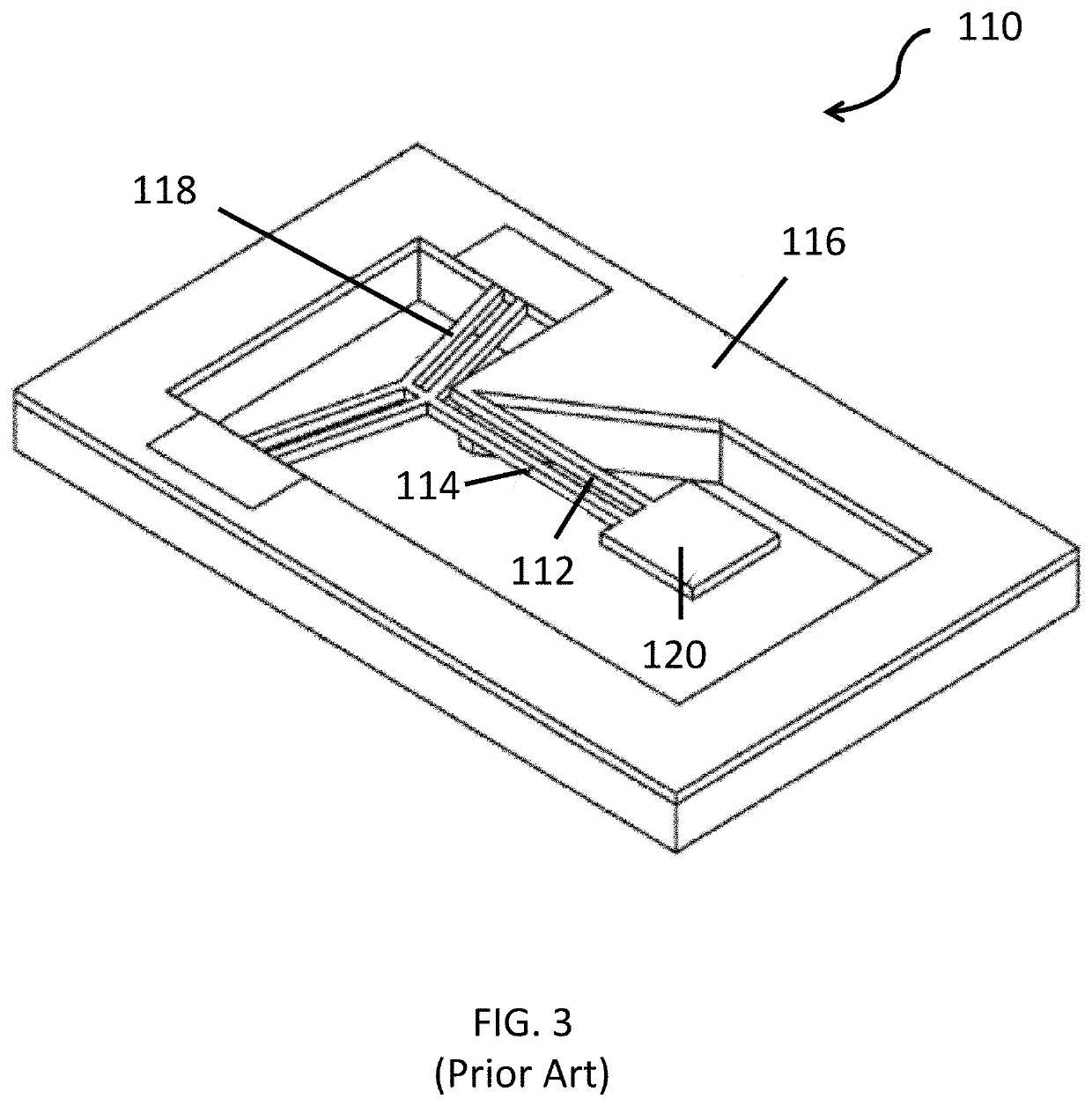
However, conventional thermoelectric MEMS structures consume large amounts of energy, which limits their applications.

Method used


Image

  • Large motion latching microelectromechanical displacement structures
  • Large motion latching microelectromechanical displacement structures
  • Large motion latching microelectromechanical displacement structures

Examples


Embodiment Construction

[0010]The following detailed description is of the best currently contemplated modes of carrying out the present disclosure. The description is not to be taken in a limiting sense, but is made merely for the purpose of illustrating the general principles of the present disclosure, because the scope of the present disclosure is defined by the appended claims.

[0011]As used herein, the singular forms “a,”“an,” and “the” include the plural reference unless the context clearly dictates otherwise.

[0012]Except where otherwise indicated, all numbers expressing quantities of ingredients, reaction conditions, and so forth used in the specification and the claims are to be understood as being modified in all instances by the term “about.” Further, any quantity modified by the term “about” or the like should be understood as encompassing a range of ±10% of that quantity.

[0013]For the purposes of describing and defining the present disclosure, it is noted that the term “substantially” is utilize...


PUM


Abstract

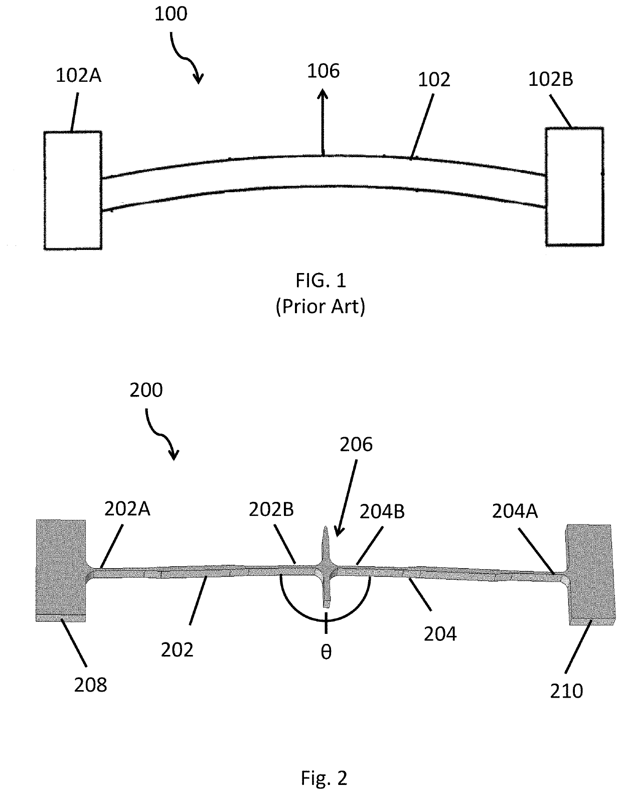
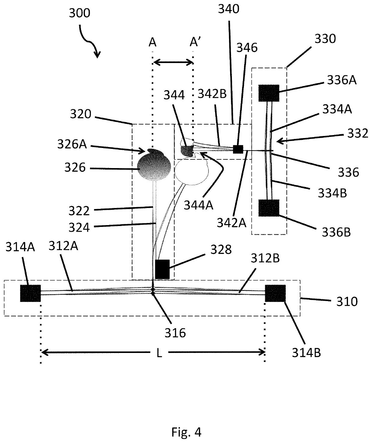
A planer silicon-based displacement amplification structure and a method are provided for latching the displacement. The displacement amplification structure may include a first actuation beam and a second actuation beam coupled to the first beam with an angle, the ends of the first beam and the second beam coupled to fixture sites, and an end of the second beam coupled to a motion actuator; a motion shutter coupled to an opposing end of the first and second beams; and a latching thermoelectric displacement structure blocking the shutter return path and have faster response than the shutter structure.

Description

TECHNICAL FIELD[0001]The present disclosure relates to a microelectromechanical systems (MEMS) and, in particular, to a MEMS structure that can latch a large displacement after power is removed.BACKGROUND[0002]MEMS actuation technologies can be categorized into electrostatic, thermoelectric, and electromagnetic. Electrostatic technology is commonly used in MEMS structures and has the advantage of low power consumption and ease in achieving multiple directional motions. In additional to potential stiction issues due to their large surface area-to-volume ratio, electrostatic MEMS have a disadvantage in that they require hematic sealing to prevent moisture-induced high electrical field shorting, resulting in increased cost. Electromagnetic MEMS requires integration of coils or magnets, which is not compatible with conventional MEMS processes, leading to difficulties in production. Thermoelectric MEMS structures have a relatively simple device configuration that can be produced by a low...

Claims


Application Information

Patent Timeline
IPC IPC(8): G02B26/08B81B7/00B81B7/02
CPCG02B26/0841B81B7/008B81B7/02B81B2201/031B81B2201/042B81B2207/015B81B2207/07B81B3/0054B81B2201/045G02B26/0866
Inventor ZHAO, JINGCHE, XIANGCHEN
Owner AGILTRON
Learn More