Separator and energy storage device

a technology of separator and energy storage device, which is applied in the direction of cell separator/membrane/diaphragm/spacer, cell components, electrical equipment, etc., can solve the problems of reducing the cycle capacity of lithium-ion batteries, and achieve the reduction of the probability of pore blockage due to compression and swelling in the separator, good safety performance, and good protection from being destroyed

Active Publication Date: 2021-03-30
NINGDE AMPEREX TECH
View PDF8 Cites 1 Cited by
  • Summary
  • Abstract
  • Description
  • Claims
  • Application Information

AI Technical Summary

Benefits of technology

[0004]A separator and an energy storage device are provided according to the present application. With the separator provided by the application, not only the problem of the gap between the separator and the electrode can be solved, but also excellent adhesive force between the separator and the electrode can be maintained; moreover, the rate performance and cycle performance of the energy storage device can be improved due to the pore structures maintained in the separator of the application.
[0023]An excellent adhesion exists between the separator and the electrode according to the present application, thus ensuring that the energy storage device has good safety performance. Moreover, the porous layer is arranged on a surface of the separator, and the inorganic particles contained in the pores in the porous layer can serve to support the pores, and therefore the pores can be well protected from being destroyed. As such, the probability of pore blockage due to compression and swelling in the separator is reduced, the separator would exhibit high ionic conductivity, and the rate performance and cycle performance of the energy storage device are greatly improved.

Problems solved by technology

In the cycle process of the lithium-ion battery, with the progress of charging and discharging, there will be a gap between the electrode and the separator, resulting in a reduction of the cycle capacity of the lithium-ion battery and thereby having an influence on its service life.

Method used


Image

  • Separator and energy storage device
  • Separator and energy storage device

Examples


example 1

[0077]The preparation method is the same as that of comparative example 1, except that the ratio of the Dv90 of the inorganic particles in the porous layer to the thickness of the porous layer is 0.3 in Example 1.

example 2

[0078]The preparation method is the same as that of comparative example 1, except that the ratio of the Dv90 of the inorganic particles in the porous layer to the thickness of the porous layer is 0.5 in Example 2.

example 3

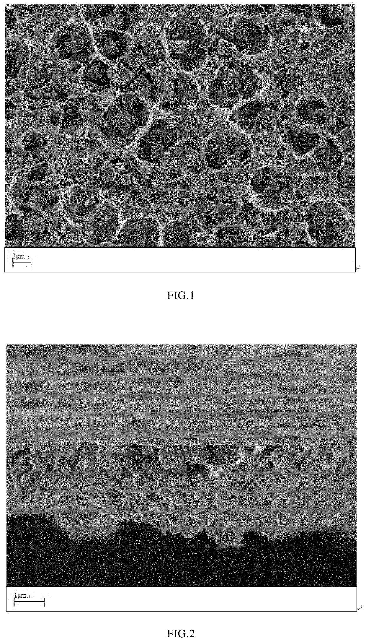
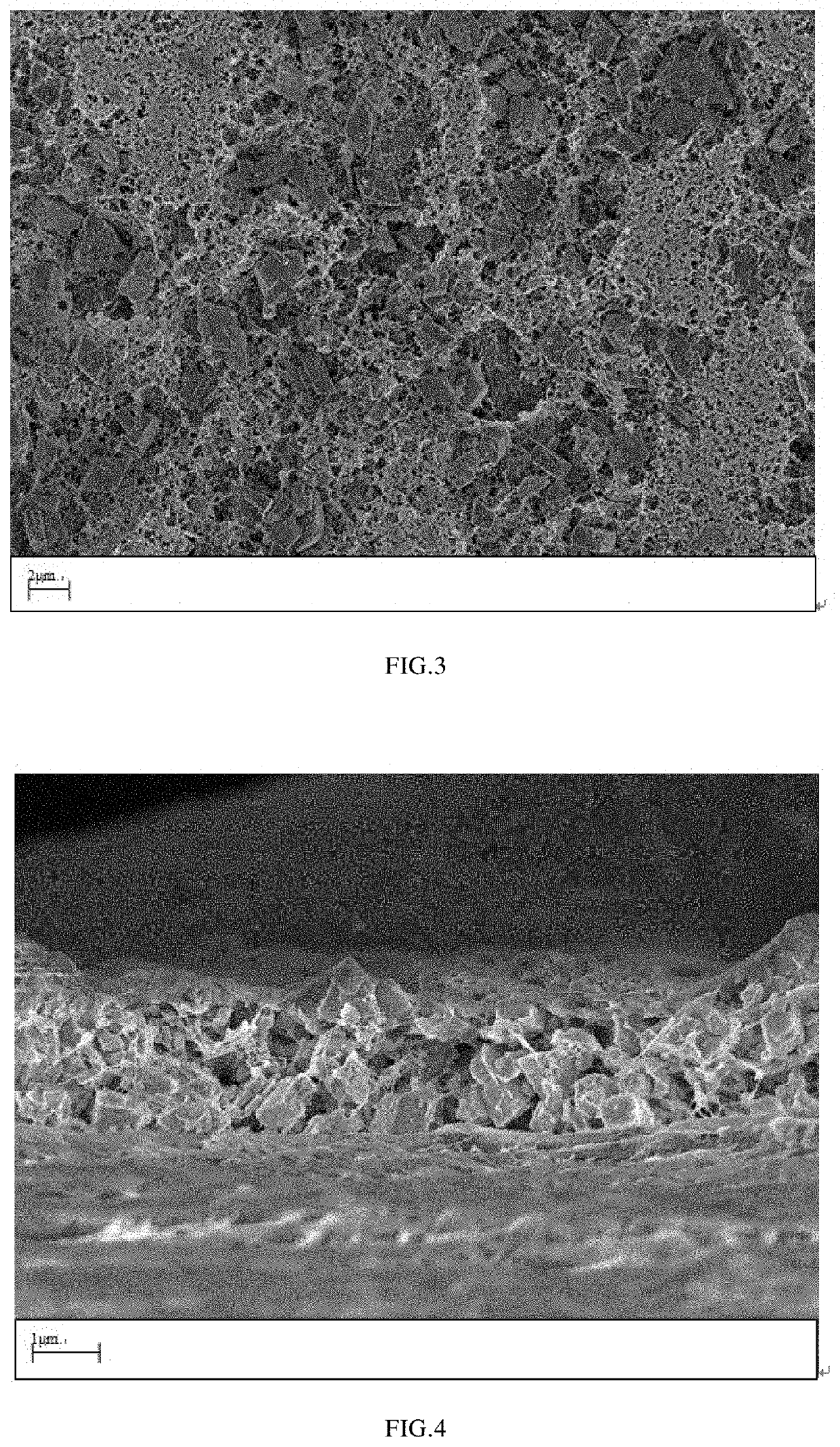
[0079]The preparation method is the same as that of comparative example 1, except that the ratio of the Dv90 of the inorganic particles in the porous layer to the thickness of the porous layer is 0.8 in Example 3. As can be seen in FIGS. 1-2, FIG. 1 is an electronic microscope image (3000 times magnification) of pores of a lower surface of the porous layer in example 3, FIG. 2 is an electronic microscope image (10,000 times magnification) of the cross section of the porous layer in the thickness direction in example 3.


PUM

PropertyMeasurementUnit
thicknessaaaaaaaaaa
pore sizeaaaaaaaaaa
volume ratioaaaaaaaaaa

Abstract

The application provides a separator and an energy storage device. The separator comprises: a porous substrate; and a porous layer arranged on a surface of the porous substrate, wherein the porous layer comprises inorganic particles and a binder, and a ratio of Dv90 of the inorganic particles to the thickness of the porous layer is in a range from 0.3 to 3.0. Excellent adhesion exists between the separator and the electrode according to the present application, which ensures that the energy storage device has good safety performance. Moreover, the rate performance and cycle performance of the energy storage device can be greatly improved due to the existence of inorganic particles in the separator.

Description

CROSS REFERENCES TO RELATED APPLICATIONS[0001]This application claims the benefit of Chinese Patent Application No. 201810321779.5 filed on Apr. 11, 2018. The entire contents of the above application are hereby incorporated by reference in their entirety.FIELD OF THE APPLICATION[0002]The application relates to the field of energy storage devices, and in particular, to a separator and an energy storage device.BACKGROUND OF THE APPLICATION[0003]Non-aqueous secondary batteries, particularly lithium-ion batteries, are widely used in portable electronic devices such as notebook computers, digital cameras, camcorders, and cellphones, due to their high energy density and good rate performance. In recent years, the application of lithium-ion batteries as the power supply for electrical vehicles, is also promoting the development of lithium-ion battery technology. In the cycle process of the lithium-ion battery, with the progress of charging and discharging, there will be a gap between the e...

Claims


Application Information

Patent Timeline
Patent Type & Authority Patents(United States)
IPC IPC(8): H01M2/16H01M2/14H01M50/449H01M10/0525H01M50/403H01M50/411H01M50/446H01M50/417H01M50/426H01M50/431H01M50/434H01M50/443H01M50/451H01M50/491
CPCH01M50/449H01M10/0525H01M50/403H01M50/411H01M50/446H01M50/491H01M50/40Y02E60/10H01M50/417H01M50/451H01M50/434H01M50/443H01M50/431H01M50/426
Inventor YI, JIANJIANZHANG, XINZHIWEI, ZENGBINTAO, XINGHUA
Owner NINGDE AMPEREX TECH
Why Eureka
Try Eureka