Three-Pole Two-Layer Photo-Rechargeable Battery

a photo-rechargeable battery and two-layer technology, applied in the field of energy storage dye-sensitive solar batteries, can solve the problems of limiting the application of individual batteries, inability to generate power, and dye-sensitive solar batteries, and achieve the effect of reducing internal resistance, reducing internal resistance, and charging curren

Inactive Publication Date: 2009-03-26
NISSAN CHEM IND LTD
View PDF3 Cites 21 Cited by
  • Summary
  • Abstract
  • Description
  • Claims
  • Application Information

AI Technical Summary

Benefits of technology

[0015]It is an object of the present invention to provide an energy storable dye-sensitized solar battery capable of resolving the above-described problems, namely, to provide an energy storable dye-sensitized solar battery capable of improving a light energy storage capacity whose maximum storage capacity is not limited by an iodine anion amount in an electrolyte solution, and capable of obtaining an adequate charging current in a short time by reducing an internal resistance.
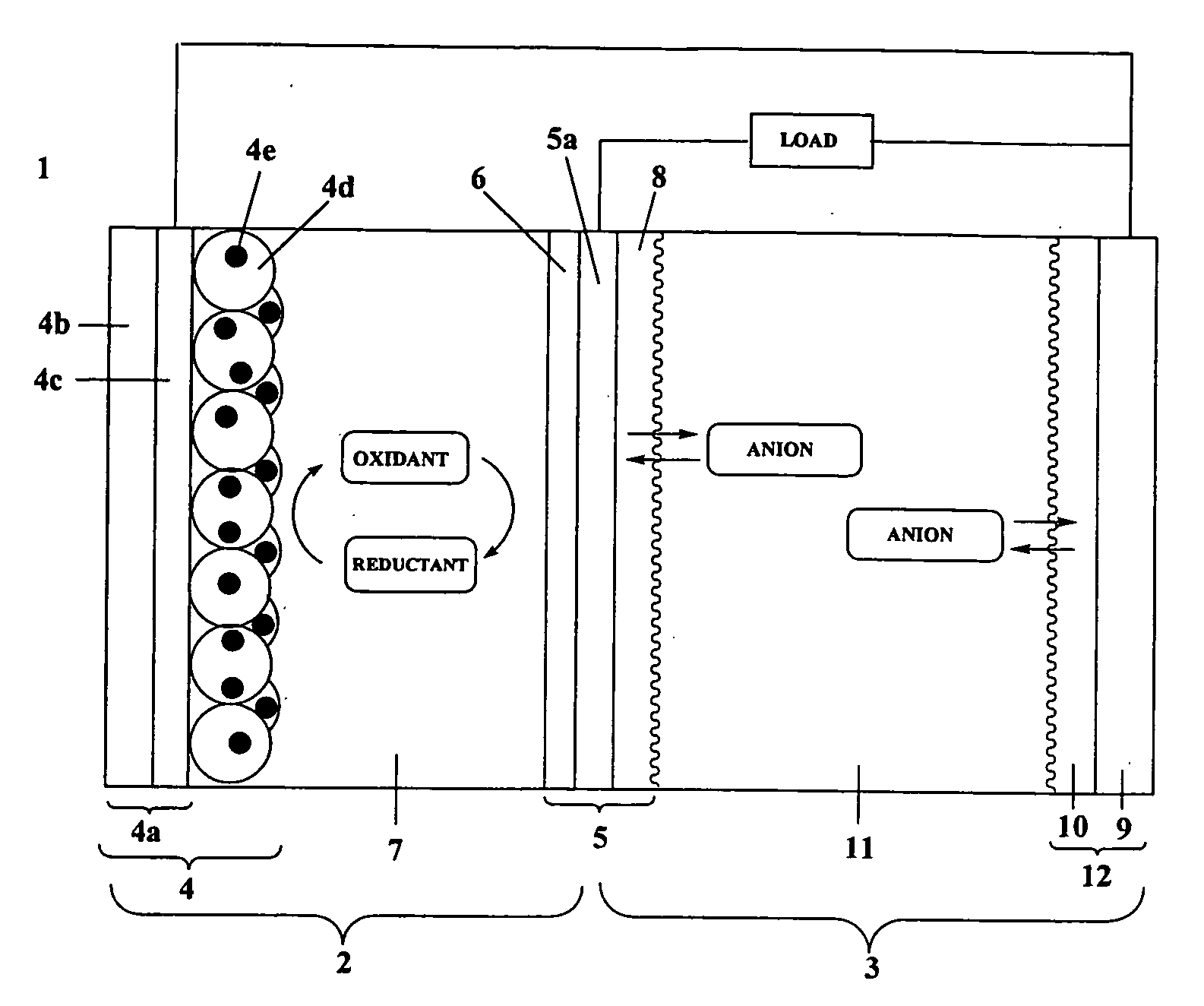
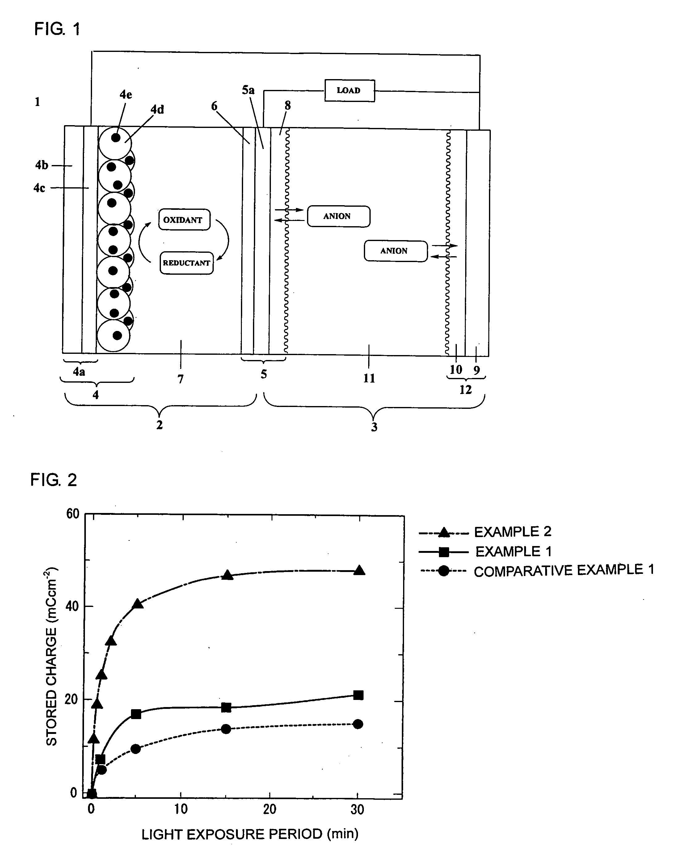
[0016]As a result of diligent research to solve the above problems, the inventors devised a way to improve a light energy storage capacity without increasing an amount of electrolyte solution, by using a three-pole two-layer structure formed from a solar battery cell and a storage cell, and by using a conductive polymer as a hole storage material. In addition, compared to a conductive polymer layer formed by electrolytic polymerization, forming the conductive polymer layer by coating a conductive polymer achieves a more uniform film and a larger surface area with a simpler process due to elimination of the polymerization process. As a consequence, a way to achieve a high light energy storage capacity was also discovered and such efforts culminated in completion of the present invention. Moreover, according to the present invention, a thin and lightweight three-pole two-layer photo-rechargeable battery can be achieved that does not require an ion exchange membrane such as described in Japanese Patent Application Publication No. JP-A-2006-172758, thus enabling a cell gap reduction as well as a reduction in the internal resistance of the charge storage electrode due to the absence of the ion exchange membrane, in addition to achieving a sufficient charging current in a shorter amount of time.
[0026]According to the present invention, a thin three-pole two-layer photo-rechargeable battery can be provided that has excellent light energy storage performance and can achieve a charging current in a shorter amount of time, without tile volume of anions in an electrolyte solution limiting the maximum storage capacity. Furthermore, optimal compositions of electrolyte solution for both the solar battery cell and the storage cell structuring the three-pole two-layer photo-rechargeable battery according to the present invention can be obtained, and it is possible to provide a photo-rechargeable battery capable of achieving a higher photoelectric conversion characteristic and a better storage characteristic compared to a conventional type of integrated photo-rechargeable battery.

Problems solved by technology

However, solar batteries including the dye-sensitized solar battery have the disadvantage of being unable to generate power in dark locations since the power generation of solar batteries is dependent on light intensity, thus limiting their application as an individual battery.
Therefore, the maximum storage capacity is limited by the amount of iodine anions.
As a consequence, an adequate charging current cannot be obtained.

Method used


Image

  • Three-Pole Two-Layer Photo-Rechargeable Battery
  • Three-Pole Two-Layer Photo-Rechargeable Battery

Examples


production example 1

Manufacture of Photo-Electrode

[0103]A TiO2 paste (Ti Nanoxide D, Solaronix) was coated on an FTO glass substrate (2 cm×2.5 cm×1 mm) using the doctor blade method. Following coating, the past was baked at 550° C. for 30 min in an electric furnace and then cooled at room temperature. After immersion for 20 hrs in a dye solution, a photo-electrode was manufactured. The dye solution used dissolved 0.3 mM of N719 (Peccell Technologies) in a mixed solvent (1:1) of acetonitrile (AN) and t-butyl alcohol.

production example 2

Manufacture of Common Electrode on Which First Conductive Polymer Layer (Polyaniline Layer) is Formed by Electrolytic Polymerization

[0104]A platinum film with a thickness of 30 nm was formed on a surface of a titanium substrate (thickness: 1 mm) using the sputtering method. On a surface of an opposite side thereof, polyaniline was subjected to electrolytic polymerization according to the following procedure. For the polymerization solution, an aqueous solution of 0.5 M aniline and 1 M HClO4 was used. For the polymerization method, a controlled potential electrolytic polymerization method at +0.8 V (vs. SCE) was used. The electrolytic polymerization volume was 1 Ccm−2. In such case, the thickness of the polyaniline layer obtained was 20 μm.

production example 3

Manufacture of Common Electrode on Which First Conductive Polymer Layer (Polyaniline Layer) is Formed by Spin Coating

[0105]A platinum film with a thickness of 30 nm was formed on a surface of a titanium substrate (thickness: 1 mm) using the sputtering method. On a surface of an opposite side thereof, a polyaniline dispersion liquid (NX-B001X, Nissan Chemical Industries) was spin-coated. The spin-coated film obtained was a relatively homogeneous film with a thickness of approximately 20 μm.


PUM


Abstract

A three-pole two-layer photo-rechargeable battery has a laminated two-layered structure that includes a solar battery cell, a storage cell, and a common electrode therebetween. The solar battery cell has a structure wherein a photo-electrode, which has a photo-sensitized dye and a semiconductor layer on a conductive substrate with optical transparency, counters via a first electrolytic solution a common electrode that has a catalyst layer on a conductive substrate. The storage cell has a structure wherein the common electrode, which has a first conductive polymer layer on a conductive substrate on a side opposite the catalyst layer, counters via a second electrolytic solution a storage cell counter electrode that has a second conductive polymer layer on a conductive substrate.

Description

[0001]The disclosure of Japanese Patent Application No. 2007-249467 filed on Sep. 26, 2007 including the specification, drawings and abstract is incorporated herein by reference in its entirety.BACKGROUND OF THE INVENTION[0002]1. Field of the Invention[0003]The present invention relates to an energy storable dye-sensitized solar battery with excellent light energy storage performance. More specifically, the present invention relates to a three-pole two-layer photo-rechargeable battery formed from a solar battery cell and a storage cell.[0004]2. Description of the Related Art[0005]Research has been conducted in the past pertaining to dye-sensitized solar batteries. In 1991 the so-called Graetzel cell developed by Graetzel, et al. of Ecole Polytechnique de Lausanne in Switzerland gained attention for having high conversion efficiency despite its simple structure. However, solar batteries including the dye-sensitized solar battery have the disadvantage of being unable to generate power...

Claims


Application Information

Patent Timeline
Patent Type & Authority Applications(United States)
IPC IPC(8): H01L31/04
CPCH01M2/1673Y02E10/542H01M10/465H01M4/667H01M50/46Y02E60/10
Inventor SEGAWA, HIROSHISAITO, YOSUKEUCHIDA, SATOSHIKUBO, TAKAYAFUJITA, SATOSHIISAJI, TADAYUKI
Owner NISSAN CHEM IND LTD
Why Eureka
Try Eureka