Electronic tool and methods for recording a meeting
a technology of electronic tools and meeting, applied in the field of electronic tools and methods for recording a meeting, can solve the problems of confusion, miscommunication, and poor support of mental maps by most existing solutions, and achieve the effect of facilitating the discovery of hardware components
- Summary
- Abstract
- Description
- Claims
- Application Information
AI Technical Summary
Benefits of technology
Problems solved by technology
Method used
Image
Examples
second embodiment
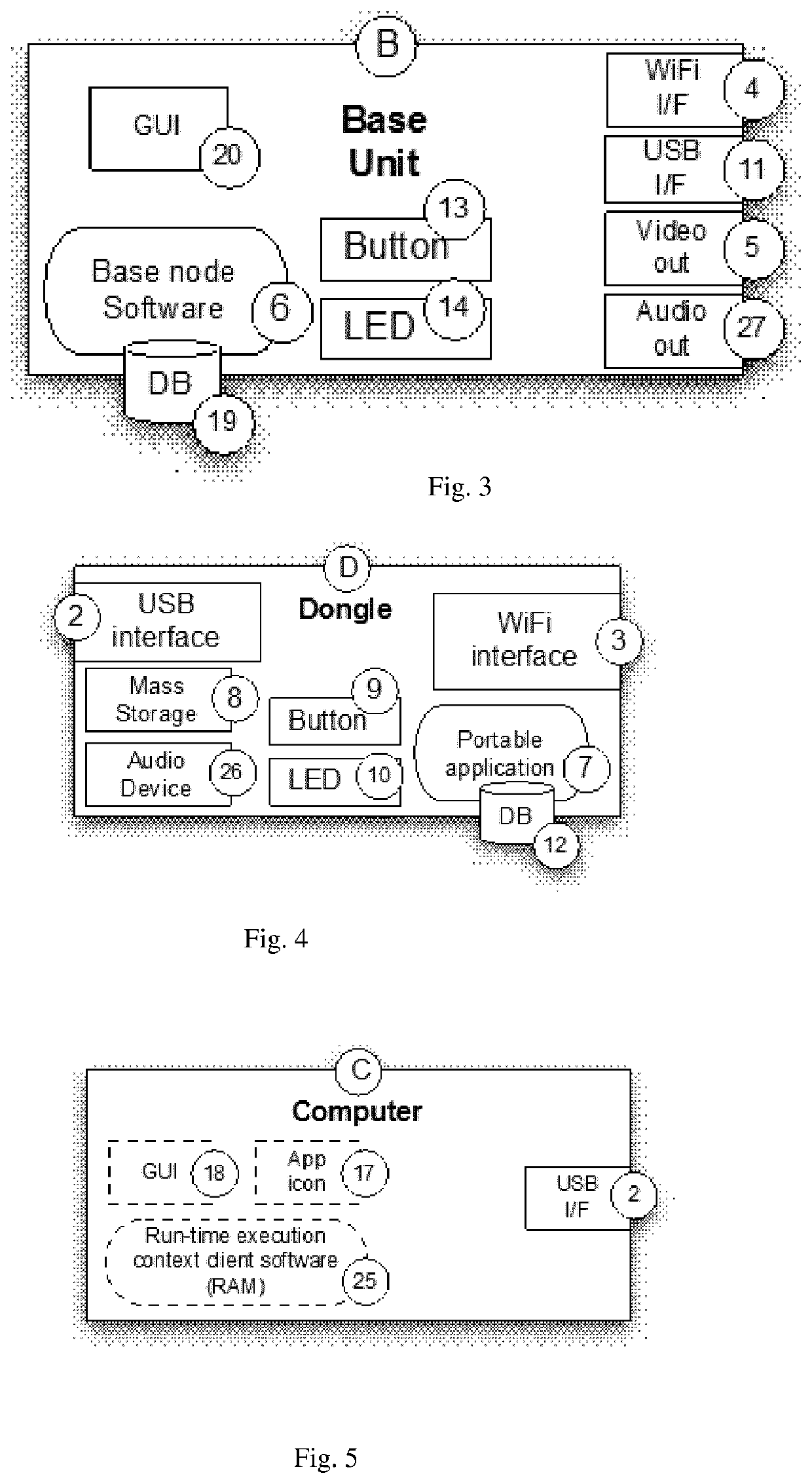
[0275]In the second embodiment, referring to FIGS. 2 to 5, the base node is a separate physical processing device called base unit (B), comprising permanent storage, memory, a processing engine, a wireless access point (4), a plug and play interface such as a USB port (11), a graphics display output adapter (5) like VGA / DP / DVI / HDMI, and optionally an audio output adapter (27). An input device having an actuator such as a button 13 and a visual indicator 14 are optional.
[0276]The connection unit is a physical device in the form of an external peripheral device (shown in the drawings as a “dongle” D) comprising permanent storage storing the portable application (7) and configuration parameters (12), memory, a processing engine (e.g. CPU, FPGA), a wireless transmitter such as WiFi (3) or other wireless transmitters such as LiFi, a plug and play interface such as a USB interface (2), a button as input device (9), an LED ring as visual indicator (10). The portable application is stored o...
third embodiment
tion Stored on Standard Solid State Memory Such as a USB Stick
[0296]In the third embodiment, the portable application is stored on a solid state memory such as a regular USB memory stick (FIG. 7).
[0297]With a solid state memory such as a regular USB memory stick, there is no input device, visual indicator or transmitter of the kinds described above for the connection unit. This means that the system needs to:[0298]Use the transmitter / receiver from the client processing device.[0299]Use as input device a key or button on the client processing device like a physical key on the keyboard, a special mouse press, a button area on a touch screen, a button displayed on the screen to be clicked on with a mouse pointer.[0300]Present the visual indicator on the client processing device's display.
[0301]The client processing device then looks like FIG. 8.
[0302]This embodiment provides a peripheral interface such as the USB interface on any processing device acting as a host device such as a comp...
fourth embodiment
ent Installed on the Client Processing Device
[0328]This embodiment is similar to the third embodiment, with as only difference that the software is copied on the client operating device (FIG. 9). In this case, no plug and play port such as a USB port is required on the client operating device.
[0329]This embodiment will typically be used for tablet PC's and mobile devices. In that case[0330]there is often no USB port available[0331]application distribution is easy and widely accepted through application stores
PUM
 Abstract
Description
Claims
Application Information
 - R&D
- Intellectual Property
- Life Sciences
- Materials
- Tech Scout
- Unparalleled Data Quality
- Higher Quality Content
- 60% Fewer Hallucinations
Browse by: Latest US Patents, China's latest patents, Technical Efficacy Thesaurus, Application Domain, Technology Topic, Popular Technical Reports.
© 2025 PatSnap. All rights reserved.Legal|Privacy policy|Modern Slavery Act Transparency Statement|Sitemap|About US| Contact US: help@patsnap.com


