
Implantable medical device with differentiated luminal and abluminal characteristics

a medical device and luminal technology, applied in the field of implantable medical devices, can solve problems such as exaggerated neointimal proliferative response, and achieve the effect of reducing surface energy

Active Publication Date: 2021-04-20
COOK MEDICAL TECH LLC
View PDF19 Cites 1 Cited by
  • Summary
  • Abstract
  • Description
  • Claims
  • Application Information

AI Technical Summary

Benefits of technology

[0010]In particular, the teachings herein are aimed at creating different surface characteristics on the luminal and abluminal surfaces of an implantable medical device in order to address the different issues associated with the implantation of such devices both short term and long term in a patient. In the preferred embodiments the device has abluminal surfaces which are optimised for carrying a therapeutic agent such as a bioactive agent, and luminal surfaces which are intended to minimise thrombosis, in particular while avoiding the need for any containment or other matrix layer on the surfaces of the medical device. In the preferred embodiments, the medical device is treated to exhibit different surface energies on its abluminal and luminal surfaces.
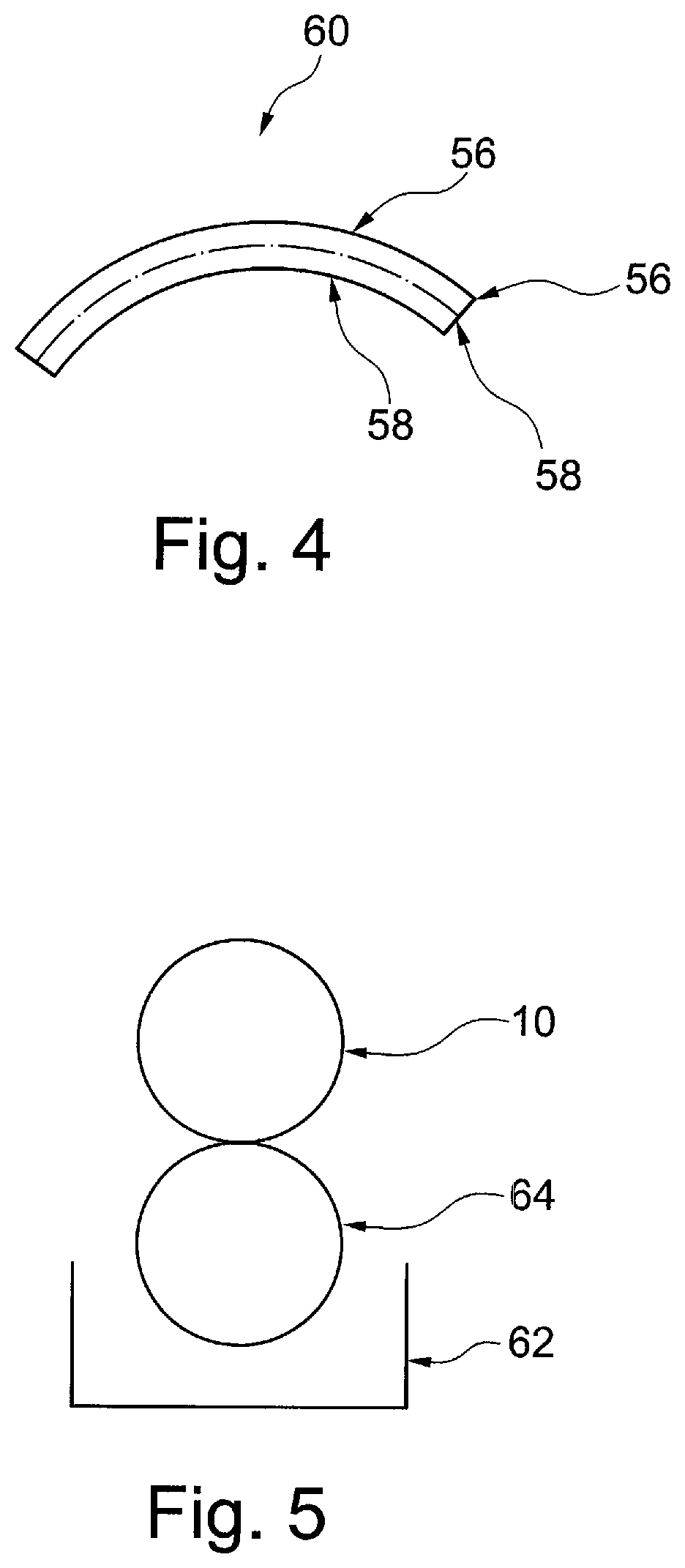
[0013]The medical device is provided with differentiated abluminal and luminal surfaces to its support structure, such that they provide different functional characteristics. In the preferred embodiment, the at least one abluminal surface has a surface energy sufficient to hold therapeutic agents, such as bioactive agents, such as drugs, thereto without the need for a containment or time release element such as a polymer or other matrix. The at least one luminal surface preferably has a much lower surface energy and such as to exhibit significantly reduced adhesion characteristics, useful in reducing the risk of thrombus formation at the luminal surface or surfaces of the structure.
[0015]The ability to avoid use of other materials or elements to hold the therapeutic and optionally bioactive material to the support structure avoids the foreign body reactions which can be experienced in clinical use with devices which use containment or time release materials.
[0016]Preferably, the coating of carbon on the at least one luminal surface is an innermost surface of the medical device. The coating of carbon can provide a substantially reduced surface energy.
[0027]treating the at least one abluminal surface of the support structure to increase the surface energy of the at least one abluminal surface relative to the at least one abluminal surface, said treatment step not being carried out on the at least one luminal surface.

Problems solved by technology

Such polymer and other layers, however, can cause complications including, for instance, inflammation and exaggerated neointimal proliferative response.

Method used


Image

  • Implantable medical device with differentiated luminal and abluminal characteristics
  • Implantable medical device with differentiated luminal and abluminal characteristics
  • Implantable medical device with differentiated luminal and abluminal characteristics

Examples


Embodiment Construction

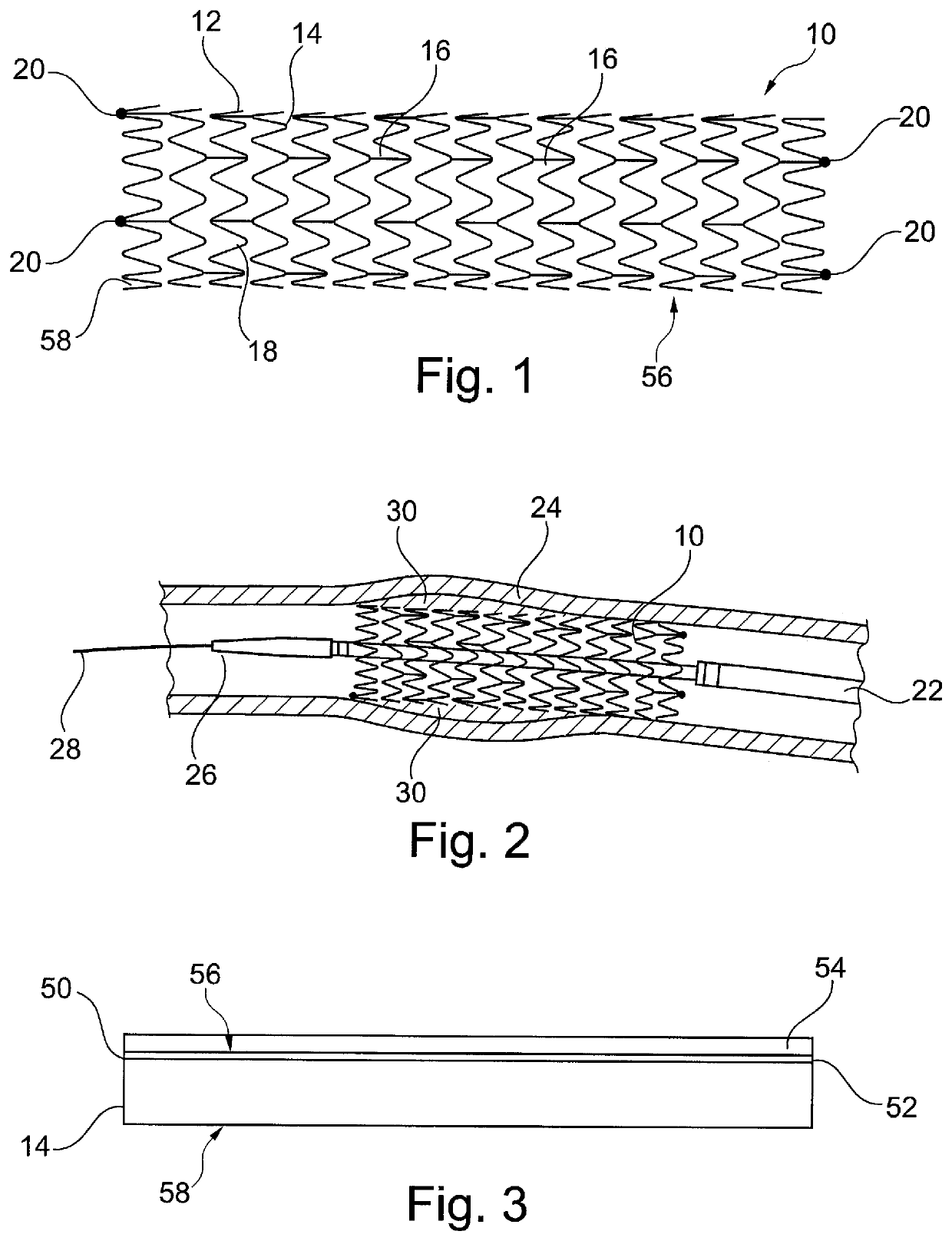
[0053]It is to be understood that the drawings are schematic only and not to scale. Often, only the principal components relevant to the teachings herein are shown in the drawings, for the sake of clarity.

[0054]The embodiments described below focus on a coated stent. It is to be understood, however, that these are examples only and that the teachings herein can be applied to a large range of medical devices, both for temporary placement in a patient and also for long term placement. Other examples include stent grafts, vascular filters and plugs, and so on.

[0055]Referring first to FIG. 1, there is shown an exemplary vascular stent 10 to which the teachings herein can be applied. The stent 10 is generally a tubular structure 12, in this example formed of a plurality of stent rings 14 which extend in series coaxially along the length of the tubular structure 12 and which are coupled to one another by means of tie bars 16, well known in the art. In this example, the stent rings 14 are ...


PUM

PropertyMeasurementUnit
depthaaaaaaaaaa
surface energyaaaaaaaaaa
time releaseaaaaaaaaaa

Abstract

There are disclosed implantable medical devices and apparatus for treating implantable medical devices during production, so as to cause the implantable medical devices to have abluminal surfaces and luminal surfaces with different functional characteristics and in particular surface energies. The luminal surfaces of the medical device are preferably coated with carbon, so as to have a low surface energy, which reduces the risk of thrombi forming when implanted into a patient's vessels. The abluminal surfaces are treated so as to have a high surface energy, such that a therapeutic, preferably bioactive, material, such as a drug, can adhere to the abluminal surfaces and preferably without any need for a containment layer such as polymer or other matrix material. Once the therapeutic material has been delivered into the tissue wall, the stent can remain within the patient's vessel without leaving any delivery artefacts, as occurs with some prior art drug eluting medical devices.

Description

CROSS REFERENCE TO RELATED APPLICATIONS[0001]This application claims the benefit of Great Britain patent application No. 1702525.5 filed on Feb. 16, 2017 and U.S. provisional patent application No. 62 / 459,844 filed on Feb. 16, 2017, entitled “Implantable Medical Device with Differentiated Luminal and Abluminal Characteristics” the entire contents of which are incorporated herein by reference.TECHNICAL FIELD[0002]The present invention relates to an implantable medical device such as a stent, stent graft, vascular filter or plug, valvuloplasty device and so on. The medical device is preferably at least partially coated with a bioactive agent, in the preferred embodiments on its abluminal surfaces.BACKGROUND OF THE INVENTION[0003]Coated medical devices, particularly endoluminally deployable medical devices, are known for a variety of medical applications. In the case of an implantable medical device, that is a device intended to be left in the patient permanently or over long periods o...

Claims


Application Information

Patent Timeline
Patent Type & Authority Patents(United States)
IPC IPC(8): A61L31/00A61L31/16A61L31/02A61L31/08A61L31/14A61L27/08A61L27/54
CPCA61L31/16A61L31/022A61L31/024A61L31/084A61L31/14A61L27/08A61L27/54A61L2400/18A61L2420/02A61F2/82A61L31/08A61L33/00B05D3/002A61F2002/823
Inventor NEILAN, JOHNMURRAY, DAVIDBUTLER, JAMES
Owner COOK MEDICAL TECH LLC
Learn More