Torque rod

a technology of torque rods and rods, which is applied in the field of torque rods, can solve the problems of difficult to obtain strength and reliability, difficult to meet the demand for space savings, etc., and achieve the effects of improving load bearing capacity, enduring performance, and space saving

Active Publication Date: 2021-04-20
SUMITOMO RIKO CO LTD
View PDF15 Cites 2 Cited by
  • Summary
  • Abstract
  • Description
  • Claims
  • Application Information

AI Technical Summary

Benefits of technology

[0008]It is therefore one object of the present invention to provide a torque rod of novel structure which is able to achieve space savings for mounting the rubber bushing provided to the lengthwise end of the rod member, while improving load bearing capability and enduring performance with respect to a large load such as a stopper load.

Problems solved by technology

Accordingly, the vehicle body requires a space around the outer peripheral member that is slightly larger than the outer peripheral member so as to avoid interference of the outer peripheral member with the vehicle body side, making it difficult to meet a demand for space savings.
This may makes it difficult to obtain strength and reliability with respect to a large load such as a stopper load due to relative abutment of the inside shaft member and the outer peripheral member of the rubber bushing.

Method used


Image

  • Torque rod
  • Torque rod
  • Torque rod

Examples


Embodiment Construction

[0040]An embodiment of the present invention will be described below in reference to the drawings.

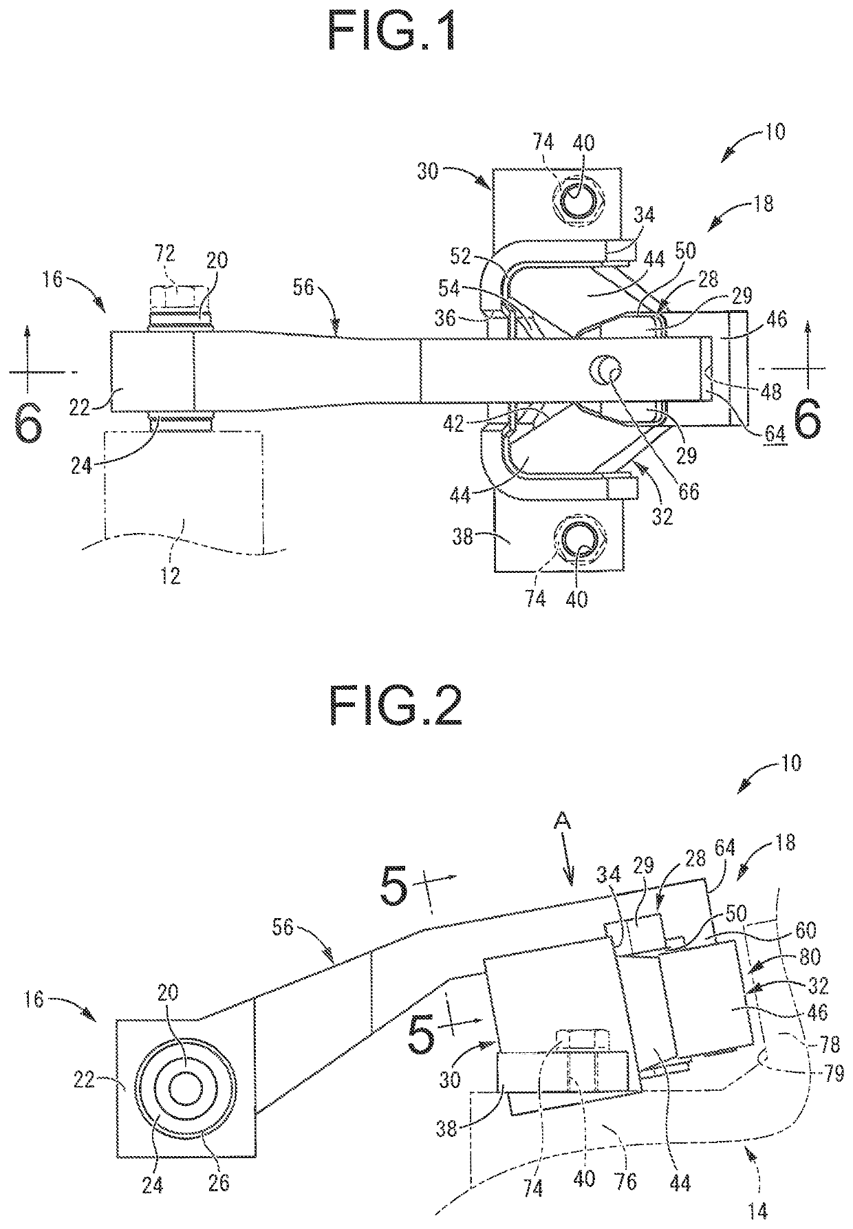
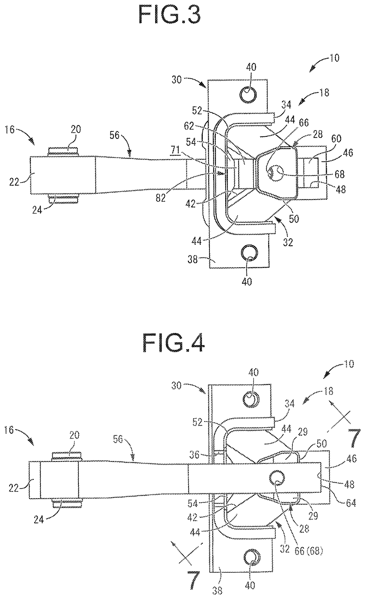
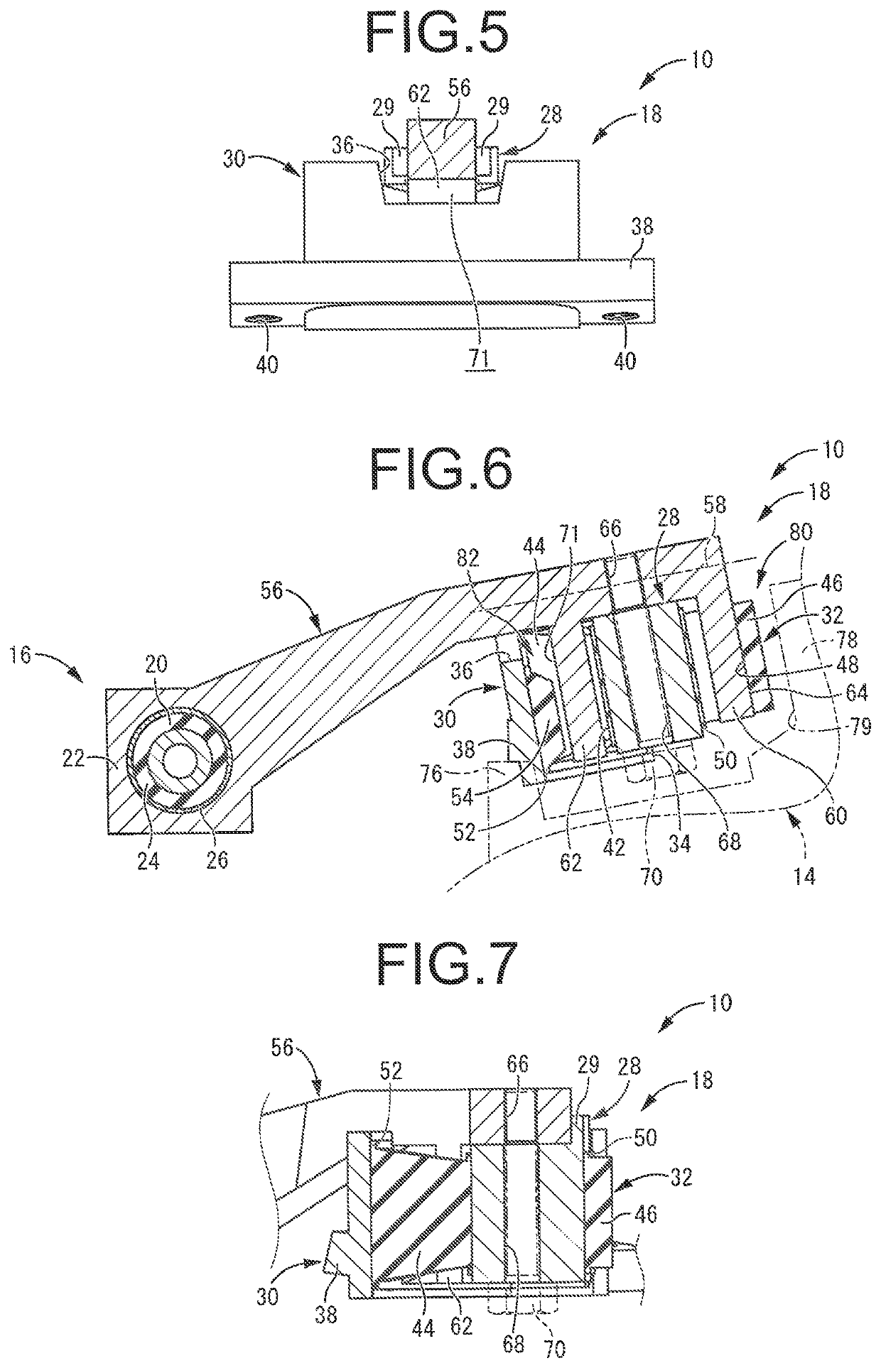
[0041]First, a torque rod 10 according to a first embodiment of the present invention is depicted in FIGS. 1 through 7. The torque rod 10 is mounted astride a power unit 12 and a vehicle body 14 serving as connection target members, and elastically connects the power unit 12 to the vehicle body 14. In general, the torque rod is mounted onto the vehicle so as to extend in the vehicle front-back direction, thus in the description hereinbelow, explanation will be given assuming that the left-right direction in FIG. 1 refers to the vehicle front-back direction. However, the torque rod 10 according to the present invention is not limited to that mounted so as to extend in the vehicle front-back direction. Besides, in the following description, the up-down direction refers to the up-down direction in FIG. 2, while the left-right direction refers to the down-up direction in FIG. 1.

[0042]Descri...


PUM


Abstract

A torque rod for straddling connection target members including a rod member and a rubber bushing provided to a lengthwise end of the rod member. The rubber bushing includes an inside shaft member, an outer peripheral member to be attached to one of the connection target members, and a rubber elastic body connecting the inside shaft member and the outer peripheral member. The rubber bushing is a part separate from the rod member and the end of the rod member is fixed to the inside shaft member. The rod member includes an abutting face to abut against the one of the connection target members without interposing the outer peripheral member of the rubber bushing. A stopper to limit an amount of elastic deformation of the rubber elastic body in the rubber bushing is constituted by including the abutting face of the rod member.

Description

INCORPORATED BY REFERENCE[0001]This application is a Continuation of International Application No. PCT / JP2017 / 042663 filed Nov. 28, 2017, which claims priority under 35 U.S.C. §§ 119(a) and 365 of Japanese Patent Application No. 2017-086058 filed on Apr. 25, 2017, the disclosures of which are expressly incorporated herein by reference in their entireties.BACKGROUND OF THE INVENTION1. Field of the Invention[0002]The present invention relates generally to a torque rod used for connecting a power unit to a vehicle body in an automobile, for example. More particularly, the present invention pertains to a torque rod including a stopper for limiting an amount of relative displacement between the components connected to each other, as well as to a rod member and a rubber bushing that constitute the torque rod.2. Description of the Related Art[0003]Conventionally, there is known a torque rod that connects a power unit and a vehicle body so as to support torque reaction force of the power un...

Claims


Application Information

Patent Timeline
Patent Type & Authority Patents(United States)
IPC IPC(8): B60K5/12F16F15/08F16F1/38F16F1/387
CPCB60K5/1291B60K5/12B60K5/1208B60K5/1241F16F1/38F16F1/3828F16F1/3873F16F15/08
Inventor TANAKA, SHINGOHAYASHI, TAKASHI
Owner SUMITOMO RIKO CO LTD
Why Eureka
Try Eureka