Thermally conductive cover for piping system, heating device for piping system, manufacturing method and attachment method for thermally conductive cover, and manufacturing method and attachment method for heating device

a technology of thermal conductor and piping system, which is applied in the direction of screws, threaded fasteners, bolts, etc., can solve the problems of uneven temperature in the pipe, and improve the workability of attachment and detachment. , the effect of improving the workability of attachment and detachmen

Active Publication Date: 2021-05-18
NICHIAS CORP
View PDF26 Cites 0 Cited by
  • Summary
  • Abstract
  • Description
  • Claims
  • Application Information

AI Technical Summary

Benefits of technology

[0006]In order to solve the above described problems, a thermally conductive cover includes a first thermal conductor for covering a piping system, the first thermal conductor being formed of metal and including a first surface on which a first hole is formed, a second thermal conductor for, coupled with the first thermal conductor, covering the piping system, the second thermal conductor being formed of metal, including a second surface on which a second hole is formed, the second surface opposing to the first surface, a coupling member including a first inserted part to be inserted into the first hole and a second inserted part to be inserted into the second hole and coupling the first thermal conductor with the second thermal conductor. At least one of the first inserted part or the second inserted part is elastically deformable in a direction perpendicular to an inserting direction of the coupling member. According to the thermally conductive cover, workability of attachment and detachment of the thermal conductor can be improved.
[0007]In order to solve the above described problems, a heating device includes the thermally conductive cover and a heater that covers the thermally conductive cover and heats the piping system through the thermally conductive cover. According to the heating device, workability of attachment and detachment of the thermal conductor can be improved.

Problems solved by technology

When a small diameter pipe is used, apart of the pipe may have a low temperature because the heater is not in closely contact with the outside of the pipe, and thus the temperature may not be uniform throughout the pipe.

Method used


Image

  • Thermally conductive cover for piping system, heating device for piping system, manufacturing method and attachment method for thermally conductive cover, and manufacturing method and attachment method for heating device
  • Thermally conductive cover for piping system, heating device for piping system, manufacturing method and attachment method for thermally conductive cover, and manufacturing method and attachment method for heating device
  • Thermally conductive cover for piping system, heating device for piping system, manufacturing method and attachment method for thermally conductive cover, and manufacturing method and attachment method for heating device

Examples


Embodiment Construction

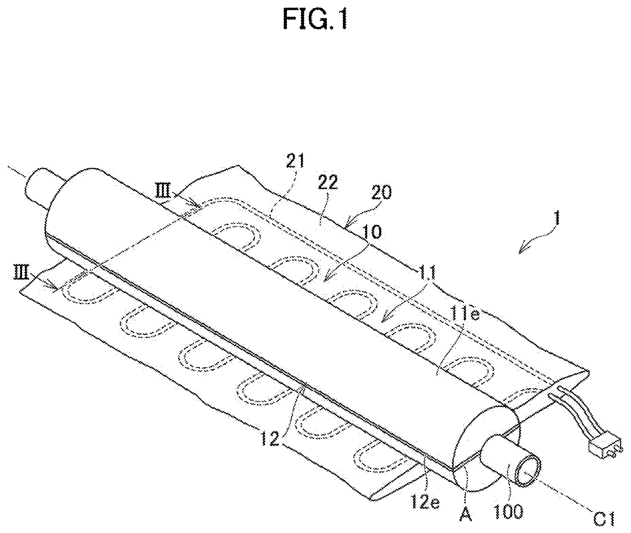
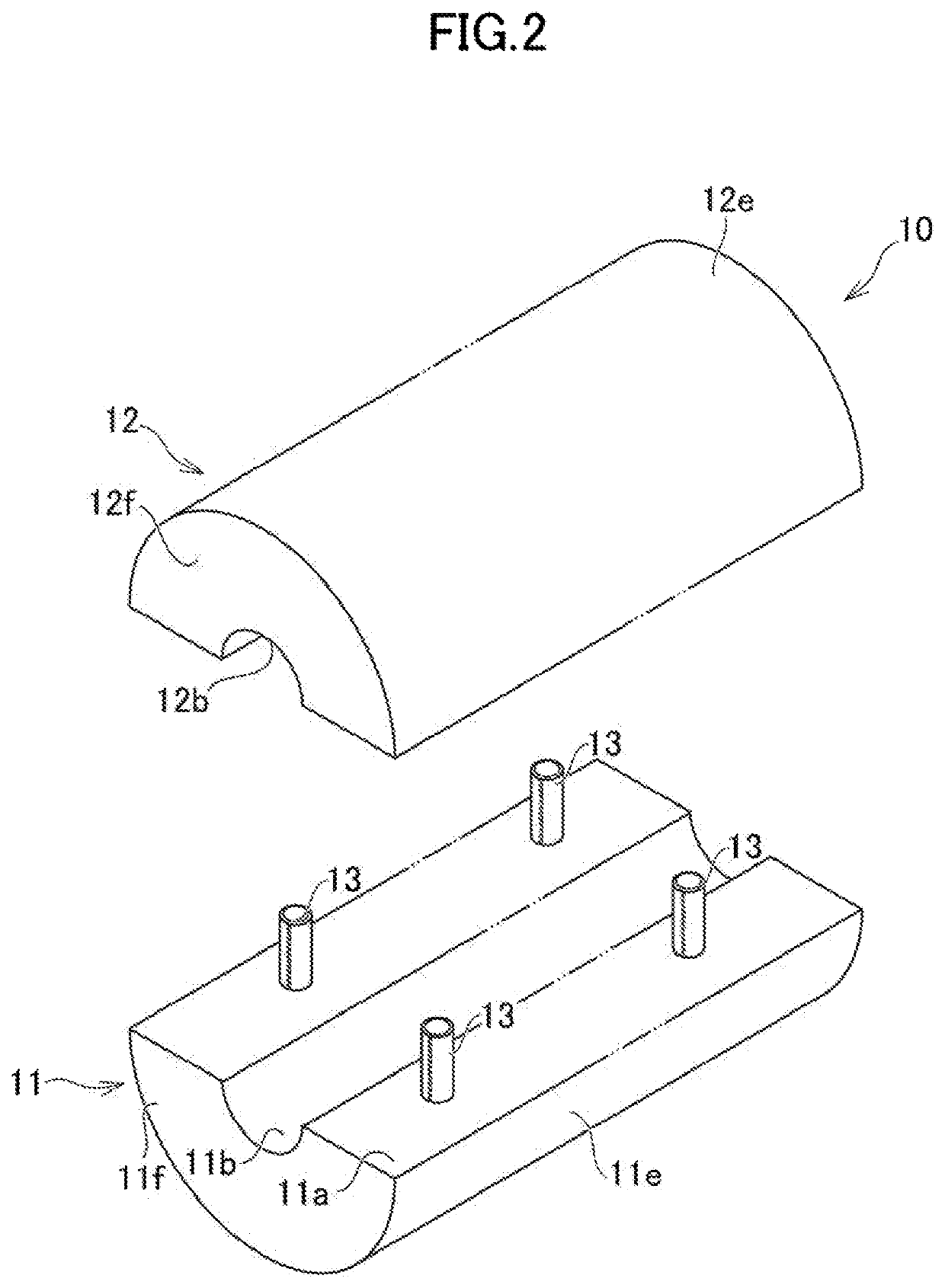
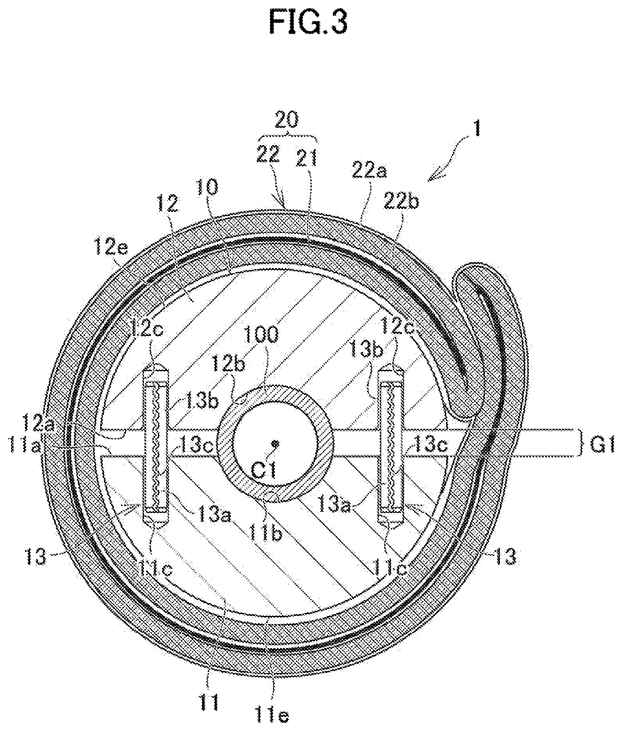
[0019]Embodiments of the present invention will be described below in detail. FIG. 1 is a perspective view of a heating device 1, which is an example of an embodiment of the present invention. FIG. 1 shows a heater 20 being open. FIG. 2 is an exploded perspective view of a thermally conductive cover 10 included in the heating device 1. FIG. 3 is a cross sectional view of the heating device 1 taken along the line III-III in FIG. 1. FIG. 3 is different from FIG. 1 in that the heater 20 covers the outside of the thermally conductive cover 10. FIG. 4 is an enlarged view of FIG. 3. FIG. 5 is a cross sectional view of FIG. 4 taken along the line V-V in FIG. 4.

[0020]The heating device 1 includes a thermally conductive cover that covers the outside of the piping system, and includes a heater that covers the outside of the thermally conductive cover and heats the piping system. Here, the piping system includes a pipe, a valve connected to the pipe, a coupling of the pipe, and an elbow, for e...


PUM

PropertyMeasurementUnit
diameteraaaaaaaaaa
diameteraaaaaaaaaa
thicknessaaaaaaaaaa

Abstract

A thermally conductive cover improves workability of attachment and detachment. The thermally conductive cover includes a first thermal conductor on which a coupling hole is formed and a second thermal conductor on which a coupling hole is formed. The thermally conductive cover further includes a coupling member having a first inserted part to be inserted into the coupling hole and a second inserted part to be inserted into the coupling hole. At least one of the inserted parts is elastically deformable in a direction perpendicular to an inserting direction of the coupling member.

Description

TECHNICAL FIELD[0001]The present invention relates to a thermally conductive cover for covering a piping system including pipes and valves coupled to the pipes, and a heating device for heating the piping system.BACKGROUND ART[0002]Devices including a pipe where fluid, such as gas and liquid flows (e.g., devices for manufacturing semiconductor), may have a heater outside the pipe so as to keep the fluid at a high temperature. When a small diameter pipe is used, apart of the pipe may have a low temperature because the heater is not in closely contact with the outside of the pipe, and thus the temperature may not be uniform throughout the pipe. To prevent this from occurring, a block formed of a high thermal conductivity material, such as aluminum, has been used to cover the outside of the pipe, and a heater has been used to cover the outside of the block (e.g., see Patent Literature 1). Here, such a block is referred to as “covering block”. The covering block has a cylindrical shape,...

Claims


Application Information

Patent Timeline
Patent Type & Authority Patents(United States)
IPC IPC(8): H05B3/58F16L53/38F16B19/00F16L59/00F16L58/00
CPCF16L53/38F16B19/00F16L58/00F16L59/00F16B19/02F16L53/30F16B19/002F16L53/34
Inventor YAMASHITA, KAORI
Owner NICHIAS CORP
Why Eureka
Try Eureka