
Fuel cell separator conveying device

a fuel cell separator and conveying device technology, applied in the direction of de-stacking articles, furnaces, charge manipulation, etc., can solve the problems of dirt adhesion on the sealing surface of stacked fuel cell separators, negative pressure generation, and protection sheet b>2/b> falling in the course of conveying, so as to reduce the adhesion of dirt and reduce the protection sheet

Active Publication Date: 2021-05-18
TOYOTA JIDOSHA KK
View PDF12 Cites 0 Cited by
  • Summary
  • Abstract
  • Description
  • Claims
  • Application Information

AI Technical Summary

Benefits of technology

[0005]Specifically, as illustrated in FIG. 8A, first, a protection sheet 2 is housed into a storage container 1 in the direction indicated by the arrow a, and subsequently, a fuel cell separator 4 to which gaskets 3 are attached is housed in the direction indicated by the arrow b to be stacked on the protection sheet 2. As illustrated in FIG. 8B, the protection sheets 2 and the fuel cell separators 4 are sequentially stacked alternately and stored. This reduces the dirt adhesion on the sealing surfaces of the fuel cell separators 4, and thus, the space in the work area is efficiently used.
[0008]The present disclosure has been made to solve such problems, and provides a fuel cell separator conveying device that ensures the reduced dirt adhesion on sealing surfaces of stacked fuel cell separators using protection sheets and the reduced protection sheet being left adhered when the fuel cell separator is conveyed.
[0015]The present disclosure ensures providing a fuel cell separator conveying device that ensures the reduced dirt adhesion on the sealing surfaces of the stacked fuel cell separators using the protection sheets and the reduced protection sheet being left adhered when the fuel cell separator is conveyed.

Problems solved by technology

However, directly stacking the fuel cell separators possibly causes dirt adhesion on sealing surfaces of the stacked fuel cell separators due to the gaskets.
Additionally, in the case where the fuel cell separator 4 is lifted up at a relatively high speed, there occurs a problem that a negative pressure is generated between the lower surface on the opposite side of the lifting up direction of the fuel cell separator 4 and the protection sheet 2, that is, between the fuel cell separator 4 and the protection sheet 2 thereunder, and the protection sheet 2 is lifted up together with the fuel cell separator 4.
Furthermore, if the protection sheet 2 is lifted up together with the fuel cell separator 4, there also occurs a problem that the protection sheet 2 may fall in its course of conveyance.
As with the one described in JP 2007-280879 A, even when the air layer is simply provided between the separator and the protection sheet, a slight negative pressure is generated when the separator is grasped, and there occurs a problem that the protection sheet is lifted up just by this slight negative pressure.

Method used


Image

  • Fuel cell separator conveying device
  • Fuel cell separator conveying device
  • Fuel cell separator conveying device

Examples


first embodiment

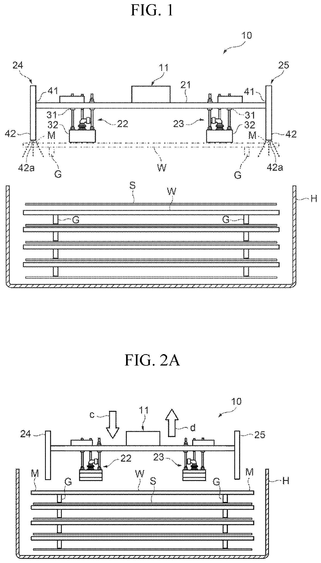
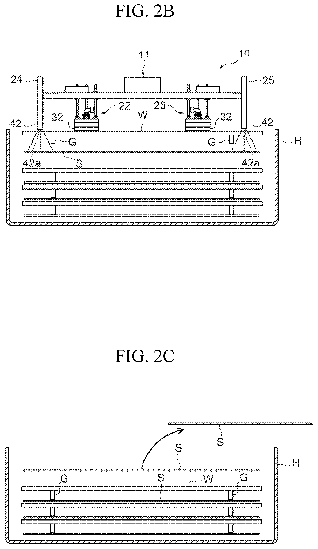
[0025]The fuel cell separator conveying device 10 includes a main body 11 illustrated in FIG. 1, a compressed air supply unit, a moving unit, a protection sheet taking-out unit, and a control unit, which are not illustrated. The fuel cell separator conveying device 10 is to lift up and convey a fuel cell separator W placed on a protection sheet S. The fuel cell separator conveying device 10 has a configuration in which, for example, a plurality of the fuel cell separators W stacked inside a storage container H with the protection sheets S interposed in-between are lifted up one by one while the protection sheet S is caused to come off, so as to take the fuel cell separator W out of the storage container H and convey the fuel cell separator W.

[0026]The fuel cell separator W includes a metal plate such as a steel plate, a stainless steel plate, and an aluminum plate, and produced by press forming. The fuel cell separator W is configured such that a surface treatment of, for example, a...

second embodiment

[0058]In the fuel cell separator conveying device 10 according to the first embodiment, a description has been given of a configuration in which the protection sheet S is caused to come off using the air blowing portions 24 and 25 as the pressing portion. However, in the fuel cell separator conveying device 20 according to the present disclosure, another configuration other than the air blowing portions 24 and 25 may be used as the pressing portion.

[0059]The following describes the fuel cell separator conveying device 20 according to the second embodiment in which the fuel cell separator conveying device according to the present disclosure is configured of weight pressing portions 24A and 25A instead of the air blowing portions 24 and 25 with reference to the drawings. Components similar to those of the fuel cell separator conveying device 10 according to the first embodiment are attached by reference numerals identical to the components of the fuel cell separator conveying device 1...


PUM

PropertyMeasurementUnit
speedaaaaaaaaaa
speedaaaaaaaaaa
speedaaaaaaaaaa

Abstract

A fuel cell separator conveying device that ensures reducing dirt adhesion on a sealing surface of a stacked fuel cell separator using a protection sheet and reducing the protection sheet being left adhered when the fuel cell separator is conveyed is provided. The fuel cell separator conveying device that lifts up and conveys the fuel cell separator placed on the protection sheet includes a grasping portion that grasps the fuel cell separator by a suction force, a moving unit that moves the grasping portion in a lift-up direction of the fuel cell separator, and an air blowing portion that applies a downward force in an opposite direction of the lift-up direction of the fuel cell separator to the protection sheet through an opening of the fuel cell separator when the moving unit moves the grasping portion.

Description

CROSS REFERENCE TO RELATED APPLICATIONS[0001]The present application claims priority from Japanese patent application JP 2018-030190 filed on Feb. 22, 2018, the content of which is hereby incorporated by reference into this application.BACKGROUNDTechnical Field[0002]The present disclosure relates to a fuel cell separator conveying device that lifts up and conveys a fuel cell separator.Background Art[0003]This type of fuel cell separator includes an anode side separator and a cathode side separator constituting a single cell for fuel cell, and there is disclosed a fuel cell separator in which gaskets are attached to exposed surface sides of these anode side separator and cathode side separator (see JP 2016-42481 A). There is also disclosed a fuel cell separator that reduces a state where neighboring separators suction one another by negative pressure, static electricity, or the like by forming an air layer between the neighboring separators (see JP 2007-280879 A).SUMMARY[0004]It is d...

Claims


Application Information

Patent Timeline
Patent Type & Authority Patents(United States)
IPC IPC(8): H01M8/0276B65G49/06H01M8/2404H01M8/0247
CPCH01M8/0276B65G49/061B65G49/068H01M8/0247H01M8/2404B65G2249/045B65G47/918H01M8/0202B65G2201/0214H01M8/0232H01M8/0245H01M8/0271B65G59/005B65G2249/04Y02E60/50
Inventor YANO, SHIMPEI
Owner TOYOTA JIDOSHA KK
Learn More