Apparatus and method for laser or plasma cutting of pieces of laminar material wound in coil

a technology of laminar material and apparatus, which is applied in the direction of soldering apparatus, manufacturing tools,auxillary welding devices, etc., can solve the problems of increased device dimensions, deformation of machined pieces, so as to reduce the risk of deformation and/or abrasion of the same piece, the effect of reducing the risk of deformation and/or abrasion

Active Publication Date: 2021-06-08
DALLAN S R L CASTELFRANCO VENETO
View PDF13 Cites 0 Cited by
  • Summary
  • Abstract
  • Description
  • Claims
  • Application Information

AI Technical Summary

Benefits of technology

[0017]Therefore, the main object of the present invention is to eliminate, in whole or in part, the drawbacks of the above-cited prior art, by providing an apparatus for the laser or plasma cutting of pieces of laminar material wound in coil that allows the machined pieces to be separated from both the swarf and the skeleton directly in the cutting area.
[0018]A further object of the present invention is to provide an apparatus for the laser or plasma cutting of pieces from laminar material wound in coil that allows the separation of the machined pieces from the swarf and from the skeleton directly in the cutting area to be combined with a mode for collecting the machined pieces that minimizes the risk of deformations and / or abrasions of the same pieces.
[0019]A further object of the present invention is to provide an apparatus for the laser or plasma cutting of pieces of laminar material wound in coil that is easy to manage.
[0020]A further object of the present invention is to provide an apparatus for the laser or plasma cutting of pieces of laminar material wound in coil that is simple and economical to manufacture.
[0021]A further object of the present invention is that of providing a method for the laser or plasma cutting of pieces from laminar material wound in coil which allows the machined pieces to be separated from both the swarf and the skeleton directly in the cutting area, to the benefit of the compactness of the apparatus.
[0022]A further object of the present invention is to provide a method for the laser or plasma cutting of pieces from laminar material wound in coil that allows the separation of the machined pieces from the swarf and from the skeleton directly in the cutting area to be combined with a mode for collecting the machined pieces that minimizes the risk of deformations and / or abrasions of the same pieces.

Problems solved by technology

None of the technical solutions described above make it possible to separate the machined pieces from the swarf and the skeleton directly in the machining area, but rather all require—downstream of the cutting area—an area for separating the machined pieces and the skeleton.
This increases the dimensions of the device, to the detriment of the compactness thereof.
The first limitation is that the machined pieces are collected separately from the skeleton, but not from the machining swarf.
The second limitation is related to the fact that the machined pieces may be deformed by falling onto the belt underneath the hatch.

Method used


Image

  • Apparatus and method for laser or plasma cutting of pieces of laminar material wound in coil
  • Apparatus and method for laser or plasma cutting of pieces of laminar material wound in coil
  • Apparatus and method for laser or plasma cutting of pieces of laminar material wound in coil

Examples


Embodiment Construction

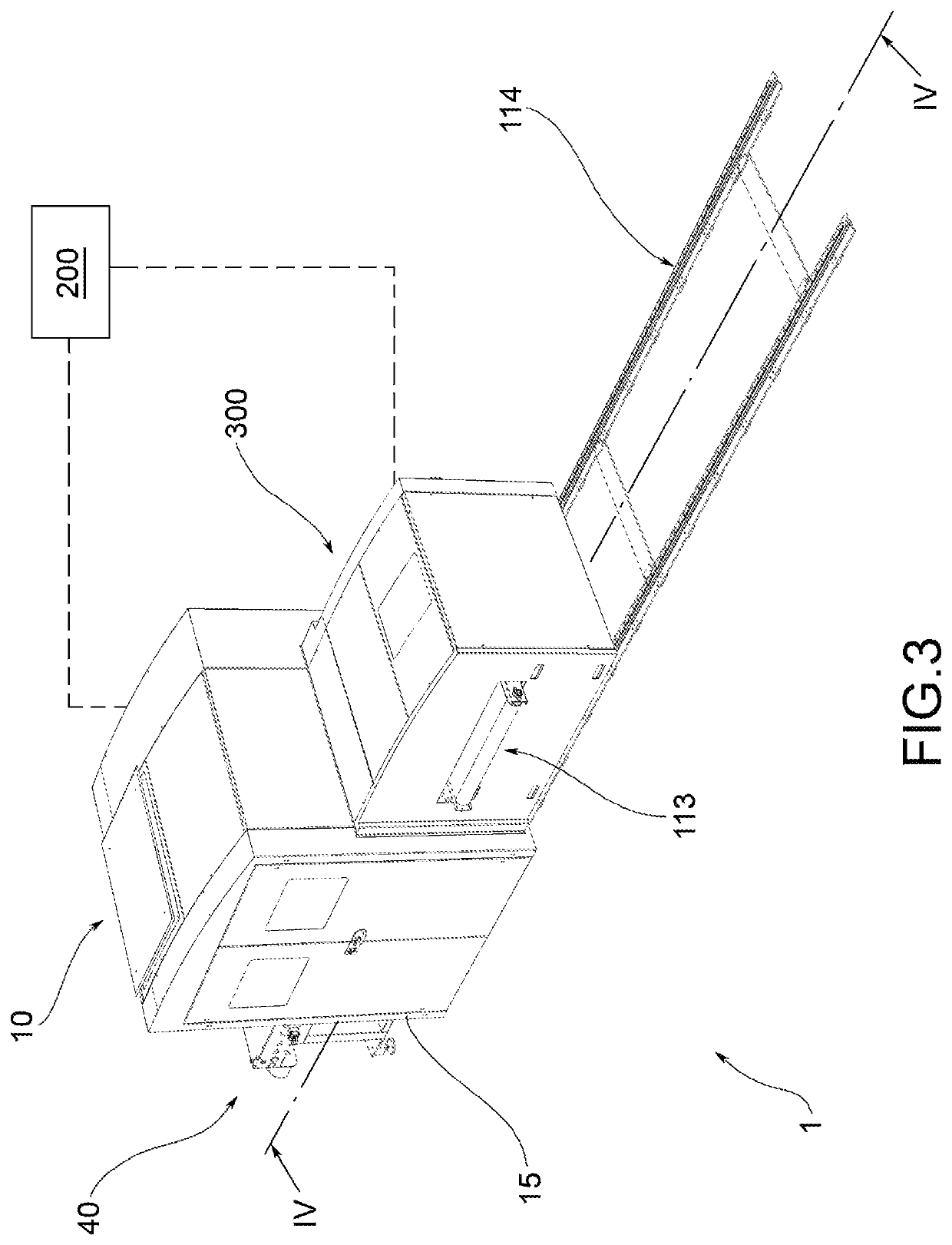
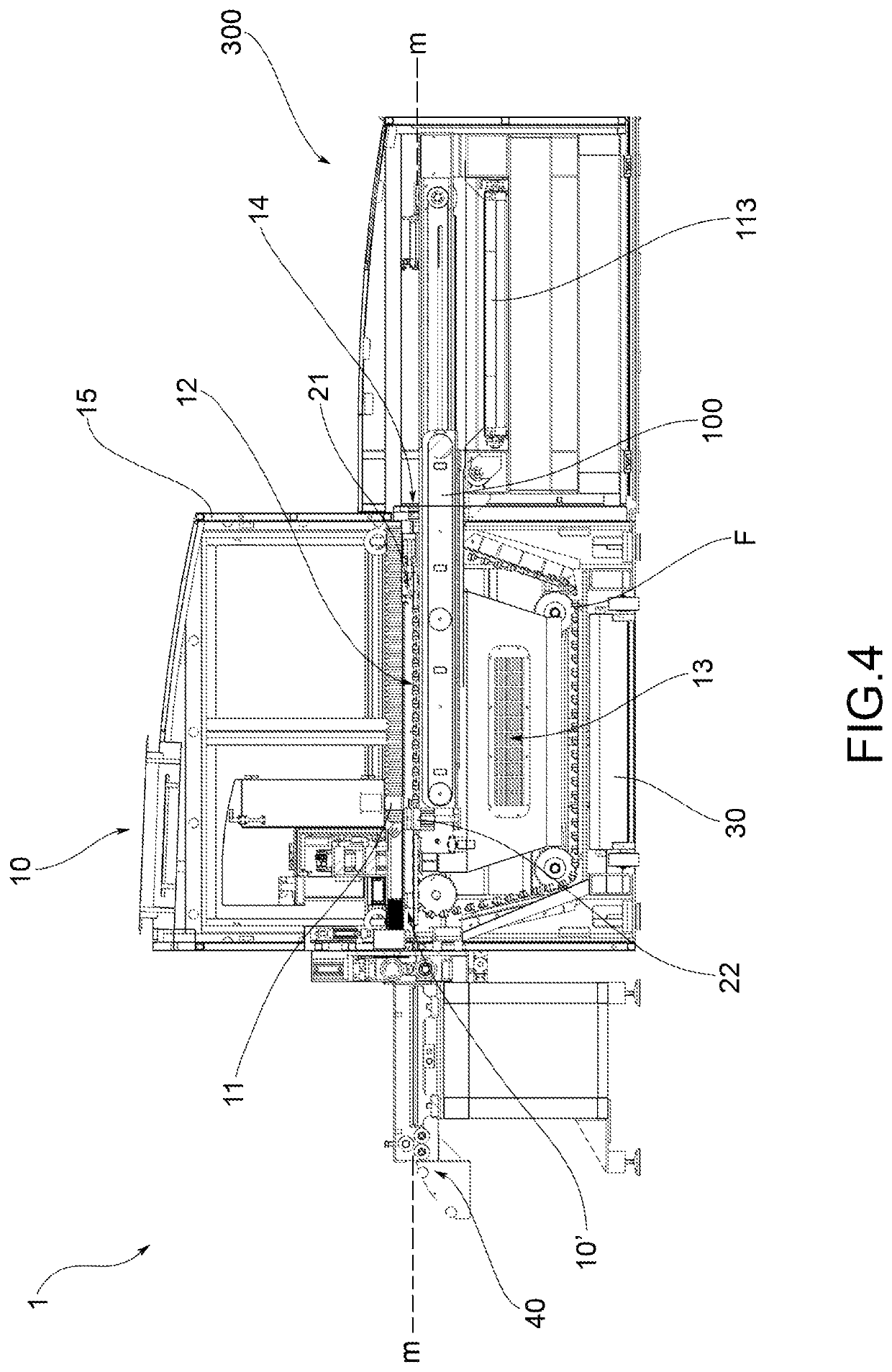
[0036]The apparatus for the laser or plasma cutting of pieces of laminar material wound in coil according to the invention shall be indicated collectively with 1 in the accompanying figures.

[0037]For sake of simplicity, the method of cutting according to the invention will be described after the apparatus, making reference to the latter.

[0038]Here and in the description and claims that follow, reference will be made to the apparatus 1 in the condition of use. It is in this sense that any references to a lower or upper position, or to a horizontal or vertical orientation, are therefore to be understood.

[0039]According to a general embodiment of the invention, the apparatus 1 comprises a cutting station 10, equipped with at least one laser or plasma cutting head 11 that is movable within an operative cutting area 12.

[0040]Such operative cutting area 12 is arranged downstream of an entrance 10′ of the laminar material in the station 10 along a longitudinal advancing direction X of the ...


PUM

PropertyMeasurementUnit
distanceaaaaaaaaaa
distanceaaaaaaaaaa
distanceaaaaaaaaaa

Abstract

A method and apparatus for laser or plasma cutting of pieces from laminar material wound in coil is provided. The apparatus provides a cutting station, with an operative cutting area and a receiving cavity, means for positioning and holding the laminar material suspended in the operative area above the receiving cavity during cutting operations, an electronic control unit and movable device for selective collection of the machined pieces. The electronic control unit controls the movement of the movable device between an active and a passive position so that that the movable device is in passive position when the cutting head is performing cutting operations generating swarf, letting such swarf to fall inside the cavity, and is in active position when the cutting head is performing cutting operations to detach pieces from the laminar material skeleton, to collect the pieces separately from the swarf and the skeleton.

Description

CROSS-REFERENCE TO RELATED APPLICATION[0001]This application claims priority to Italian Pat. App. No. 102017000111570 filed on Oct. 5, 2017, the disclosures of which are hereby incorporated by reference in their entirety.FIELD OF THE INVENTION[0002]The object of the present invention is an apparatus and a method for laser or plasma cutting of pieces from laminar material wound in coil.[0003]Advantageously, the apparatus and method according to the present invention are particularly suitable for cutting pieces that, because of their final use, must comply with high quality standards in terms of compliance with dimensional tolerances and be free of deformations and / or abrasions.[0004]In particular, the apparatus and method according to the present invention are suitable, for example, for the production of gaskets for engine heads, components for applications in the field of microelectronics and components for the eyewear sector.[0005]The laminar material that may be processed by the a...

Claims


Application Information

Patent Timeline
Patent Type & Authority Patents(United States)
IPC IPC(8): B23K26/00B23K26/38B23K10/00B23K26/08B23K26/70B23K26/16B23P21/00B23P25/00
CPCB23K26/38B23K10/00B23K26/0838B23K26/0846B23K26/0869B23K26/16B23K26/702B23P21/00B23P25/003B23P2700/12B23K37/00B23K37/0408
Inventor DALLAN, ANDREA
Owner DALLAN S R L CASTELFRANCO VENETO
Why Eureka
Try Eureka