Method for operating an electronically commutated synchronous machine, and actuation circuit

a technology of synchronous machines and actuation circuits, applied in electrical apparatus, control systems, ac motor control, etc., can solve problems such as inability to measure phase currents, inability to use single shunts, and inability to operate electronic circuits. to achieve the effect of expanding the measurement region

Active Publication Date: 2021-06-08
CONTINENTAL TEVES AG & CO OHG
View PDF7 Cites 0 Cited by
  • Summary
  • Abstract
  • Description
  • Claims
  • Application Information

AI Technical Summary

Benefits of technology

[0018]The method according to an aspect of the invention provides the advantage that torque ripples can be reduced. This is achieved in that fixed measurement points are obtained and at the same time a central arrangement of the switch-on periods is provided as soon as enough voltage is applied.
[0021]In other words, shifting always takes place when the difference between the phases is not large enough for a measurement, that is to say for example is smaller than two minimum periods when comparing the length of the switch-on periods. However, as soon as the difference is large enough for a measurement, for example is greater than two minimum periods, the switch-on periods are arranged in a centered manner. The difference between the switch-on periods is, in particular, always high when a high voltage is also applied and therefore high speeds or torques are present. Identical faults in the current can result in relatively large torque ripples at high voltages, this causing a relatively poor NVH (Noise Vibration Harshness) behavior. An aspect of the invention has the advantage that a centered arrangement of the switch-on periods (duty cycles) is provided for a maximum time, and therefore the torque ripple is reduced.
[0028]reducing the switch-on period for all phases when the switch-on period of the phase is greater than the period minus the minimum period.
[0031]The middle phase has to be between the minimum period and 100% minus the minimum period, so that a measurement can be carried out. This restricts the possible duty cycle. This disadvantage can be resolved and an improved method for measuring currents can be provided by the solution according to an aspect of the invention.
[0034]Modulation of the zero vectors means it is possible to change the switch-on periods. Therefore, the advantageous effect of the measurement region being expanded is achieved overall. For pulse width modulations (PWM) which are generated by means of space vectors (space vector modulation), it is then possible, for example, to measure currents for PWMs between zero and 100 percent when the minimum period is from zero to six percent of the PWM period.

Problems solved by technology

Switching effects in the inverter of the actuation circuit are a leading source of line-bound interference phenomena which can result in malfunctions in electronic circuits by way of the on-board electrical system.
However, the prior art exhibits the disadvantage that, for the measurement, it is not possible by means of a single shunt to provide centering of the switch-on periods of the individual phases with a fixed measurement point or measurement window or shifted switch-on periods with a dynamic measurement point or measurement window.
Specifically, if, for example, centering of the switch-on periods is provided and two of the switch-on periods have the same values, it is not possible to measure the currents of the phases.
In addition, the measurement windows would have to change as soon as the duty cycle changes, but this is not readily possible in most microcontrollers.
For this purpose, for example, currents are fed into the motor, but said currents cause relatively high torque ripples and relatively poor NVH (noise vibration harshness) behavior.
This has the effect that a measurement is not possible in the full PWM period.
This likewise causes more torque ripple.
However, currents cannot be measured when there is a central arrangement and two PWMs have the same values.

Method used


Image

  • Method for operating an electronically commutated synchronous machine, and actuation circuit
  • Method for operating an electronically commutated synchronous machine, and actuation circuit
  • Method for operating an electronically commutated synchronous machine, and actuation circuit

Examples


Embodiment Construction

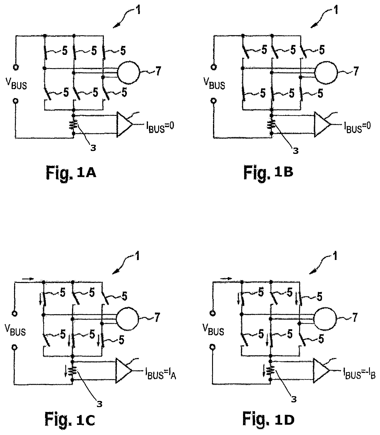
[0048]FIGS. 1A-1D show an actuation circuit 1 in various switching states with only one measurement resistor 3. Switches 5 of the actuation circuit 1 can be either open or closed. A lower switch 5 and an upper switch 5 produce a half-bridge in each case. In this case, current flows in the closed state. The current is supplied to an electronically commutated synchronous machine 7.

[0049]In FIG. 1A, all lower switches 5 are open while all upper switches 5 are closed. Therefore, all phases are short-circuited and current is not measured across the measurement resistor 3. A zero vector can be produced by this switching state. The same applies to FIG. 1B in which the upper switches 5 are open and the lower switches 5 are closed.

[0050]In contrast, FIGS. 1C and 1D do not shown the representation of zero vectors. In FIG. 1C, an upper switch 5 and two lower switches 5 are closed. Therefore, a current is measured across the measurement resistor 3. One of the six active voltage space vectors is...


PUM


Abstract

A method for operating an electronically commutated synchronous machine with several phases, wherein an actuation circuit operates the synchronous machine, the actuation circuit having at least two switches for each phase and a degree of actuation for each phase being periodically ascertained by the actuation circuit, wherein the switch-on period, during which a supply voltage is applied to the respective phase by way of the associated switch, is determined for ascertaining the degree of actuation, wherein the following steps are carried out: measuring current by a single measurement resistor in at least two measurement windows and shifting one or more of the switch-on periods of the different phases relative to one another as soon as the difference between switch-on instants of at least two phases falls below a minimum period or the difference between the switch-on periods of at least two phases falls below twice the minimum period.

Description

CROSS REFERENCE TO RELATED APPLICATIONS[0001]This application is the U.S. National Phase Application of PCT International Application No. PCT / EP2017 / 078414, filed Nov. 7, 2017, which claims priority to German Patent Application No. 10 2017 211 196.8, filed Jun. 30, 2017, and European Patent Application No. 16198509 filed Nov. 11, 2016 the contents of such applications being incorporated by reference herein.FIELD OF THE INVENTION[0002]The invention relates to a method for operating an electronically commutated synchronous machine, and also to an actuation circuit.BACKGROUND OF THE INVENTION[0003]Electronically commutated synchronous machines with permanent excitation, also known as brushless motors, have a stator with at least two, in particular three, phase windings and a rotor with at least one pole pair which is arranged perpendicularly to the rotation axis and is formed by one or more permanent magnets which are arranged in or on the rotor. A brushless motor is supplied with curr...

Claims


Application Information

Patent Timeline
Patent Type & Authority Patents(United States)
IPC IPC(8): H02P27/08
CPCH02P27/085H02M7/42H02P2207/05
Inventor TURCANU, ALEXANDRU
Owner CONTINENTAL TEVES AG & CO OHG
Why Eureka
Try Eureka