Hydraulic distributor with valve device with active discharge in load sensing circuits

a technology of hydraulic distributor and valve device, which is applied in the direction of mechanical equipment, mechanical machines/dredgers, servomotors, etc., can solve the problems of hydraulic distributor overheating, considerable risk to the safety of the operator, and the working environment and the surrounding people, and achieve the effect of lowering pressur

Active Publication Date: 2021-06-22
WALVOIL
View PDF10 Cites 0 Cited by
  • Summary
  • Abstract
  • Description
  • Claims
  • Application Information

AI Technical Summary

Benefits of technology

[0014]An object of the present invention is to provide to the art a closed-centre, load sensing distributor which allows improving the known solutions in the context of a rational, simple, and rather cost-effective solution.
[0016]It is also an object of the present invention to provide a hydraulic closed-center distributor which is less prone to problems of an uneven temperature distribution.
[0018]Particularly, an embodiment of the present invention provides a logic element configured to send to the low-pressure line, passing through the whole distributor, a flow rate dispensed by the pump to minimize the temperature differential between the distributor body and the oil used under a non-operative condition of the spool that adjust the oil distribution towards the actuations.
[0019]A further object of the invention is also to minimize the dissipation of the flow rate delivered in the case that at least one hydraulic utility requires oil for the pump and the load present at the utility is minimum or the opening of the adjusting cursor is reduced.
[0029]A further advantage is that the double driving on the logic element, in which the LS signal coming from the utilities is also present, and which acts on the active area of said element, allows a switching at a lower pressure. Therefore, a lower power dissipation follows, given by the product between the flow rate discharged through the valve and the delivery pressure.
[0031]Another advantage is that it is possible to solve the problem whereby, under some operative conditions, the LS pressure remains trapped along its own channel, even if no utility has been actuated.

Problems solved by technology

In industrial and agricultural applications, such as those of front loaders, a known problem is that of an even heating of the hydraulic distributor.
Therefore, upon the first actuations, it is usual that a blocking of the distribution spool occurs in such positions whereby the flow rate continues to be delivered without the operator being able to bring it back to a central position, resulting in a considerable risk in the safety of the operator him / herself, but also for the working environment and the surrounding people.

Method used


Image

  • Hydraulic distributor with valve device with active discharge in load sensing circuits
  • Hydraulic distributor with valve device with active discharge in load sensing circuits
  • Hydraulic distributor with valve device with active discharge in load sensing circuits

Examples


Embodiment Construction

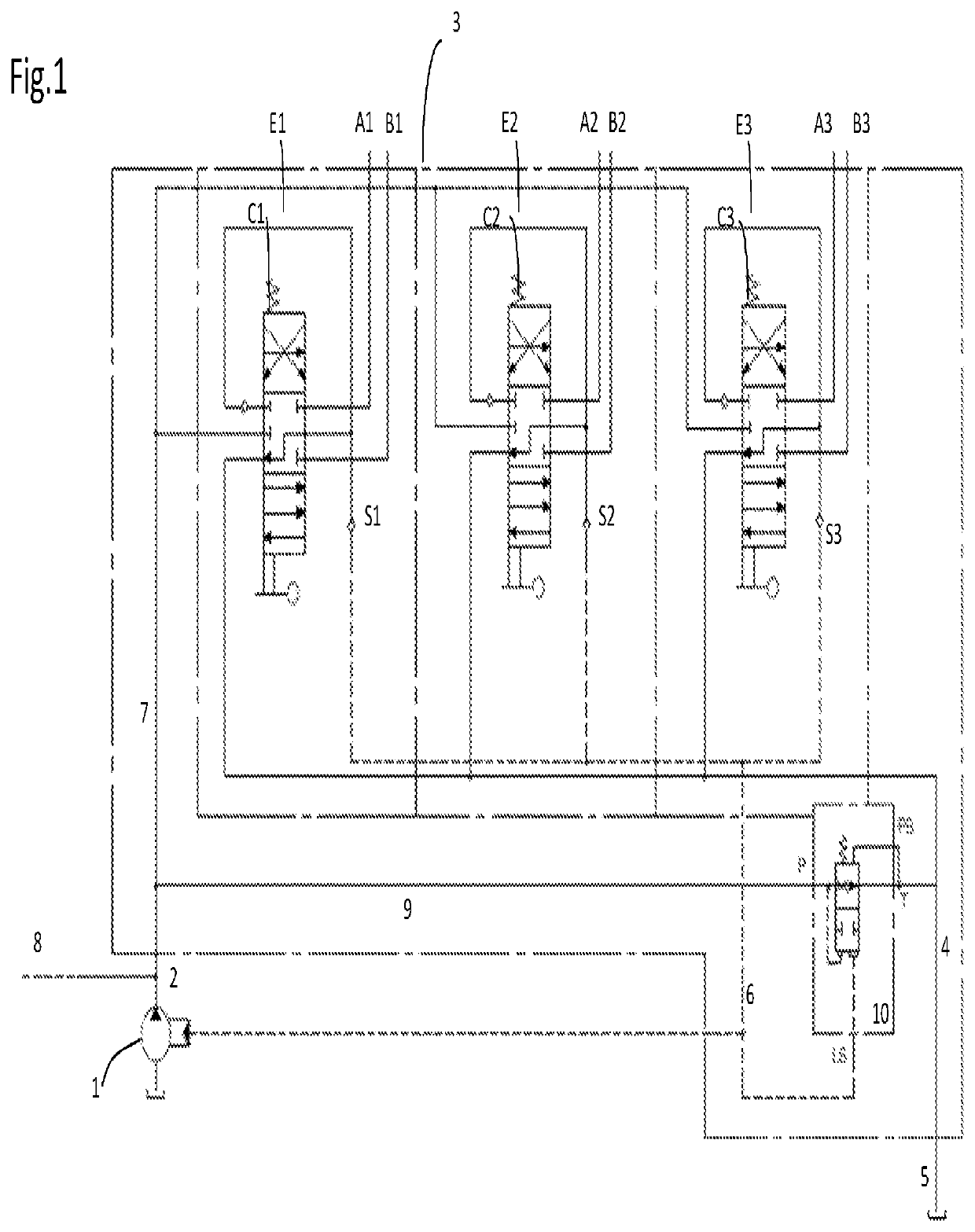
[0041]With reference to FIG. 1, an operative example of a hydraulic circuit of a distributor comprising a valve device in accordance with the invention is illustrated.

[0042]The circuit is composed of a variable displacement pump 1, connectable to a closed-center, load sensing distributor generally indicated by the reference number 3. The connection between the pump and the distributor takes place via a high-pressure channel 2, formed by a series of corresponding conduits.

[0043]In a possible embodiment, the load sensing distributor 3 is schematized by a dashed line, and it is provided with three general sections E1, E2, and E3, each of which controls a corresponding actuator through the utilities A1, B1, A2, B2, A3, and B3.

[0044]Each section E1, E2, E3 comprises therein at least one slide C1, C2, C3 and, preferably, at least one selector S1, S2 and S3 configured to capture the highest signal LS among all the utilities. Therefore, via a channel 6 the signal LS is sent to the pump 1, w...


PUM


Abstract

A distributor (3) of the closed-center, load sensing type, connected to a variable displacement pump (1) comprises a valve device (10, 110), composed of a logic element, which is pilot-operated and configured to bring a high-pressure channel (2) into communication with a low-pressure channel (4), the connection being usually opened by the combined action of an equivalent pressure generated by an elastic member (12) and a counter-pressure which is generated, under operative conditions, in the low-pressure channel (4). The connection is closed in a switching position and it is pilot-operated to a closure position by the combined action of a high-pressure signal (P) and a load sensing signal (LS).

Description

CROSS REFERENCE TO RELATED APPLICATIONS[0001]This application claims priority to Italian patent application 102017000023749 filed on Mar. 2, 2017, the contents of which are incorporated herein by reference.APPLICATION FIELD[0002]The invention is in the field of the hydraulic valve devices within directional control valves used in agricultural applications, such as in “front loader” vehicles.[0003]The invention relates to a hydraulic distributor, with a closed center and multiple working sections, and comprising a logic discharge element.[0004]According to an implementation example said logic element is an adjusting device.[0005]The invention also relates to the above-mentioned discharge adjusting device configured to be associated with a hydraulic valve distributor with multiple sections, particularly on the inside thereof.[0006]More specifically, said discharge adjusting device is a pilot-operated valve with differential areas.[0007]The driving of said valve having differential are...

Claims


Application Information

Patent Timeline
Patent Type & Authority Patents(United States)
IPC IPC(8): F15B21/04F15B11/16E02F9/22F15B13/06F16K11/07F16K11/06F15B13/08E02F3/34
CPCF15B21/04E02F9/2225F15B11/165F15B13/06E02F3/34F15B13/0871F15B2211/3111F15B2211/41563F15B2211/428F15B2211/50536F15B2211/528F15B2211/66F15B2211/851F16K11/06F16K11/07F15B2211/62
Inventor MOROTTO, AMEDEOMESTURINI, DAVIDE
Owner WALVOIL
Why Eureka
Try Eureka