Eureka AIR delivers breakthrough ideas for toughest innovation challenges, trusted by R&D personnel around the world.

Dental restoration preform and method of making the same

a dental restoration and preform technology, applied in the field of dental restoration preforms and methods, can solve the problems of increasing the amount of time a patient must wait for repair, and achieve the effects of reducing the time to create reducing the time for creating and reducing the time for a custom finished produ

Active Publication Date: 2021-06-29
JAMES R GLIDEWELL DENTAL CERAMICS
View PDF25 Cites 6 Cited by
  • Summary
  • Abstract
  • Description
  • Claims
  • Application Information

AI Technical Summary

Benefits of technology

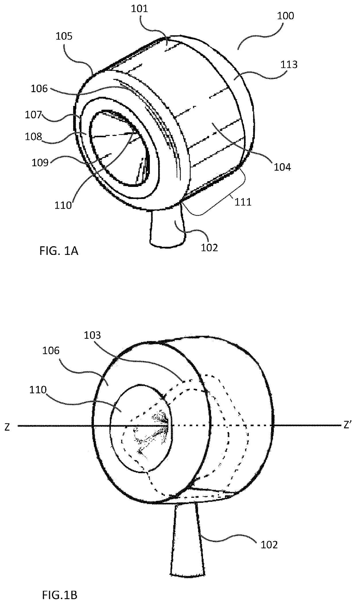
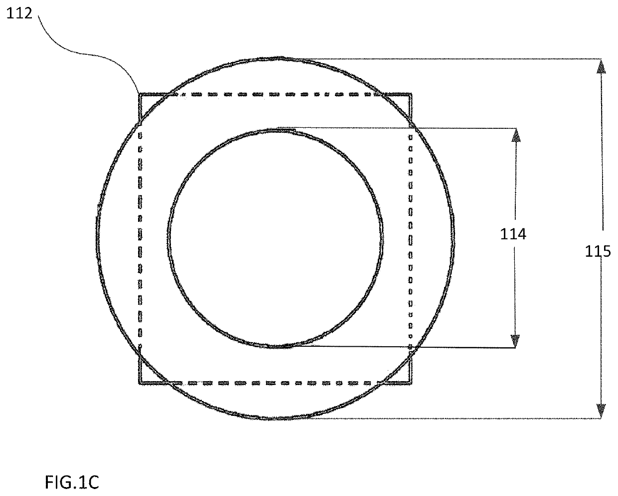
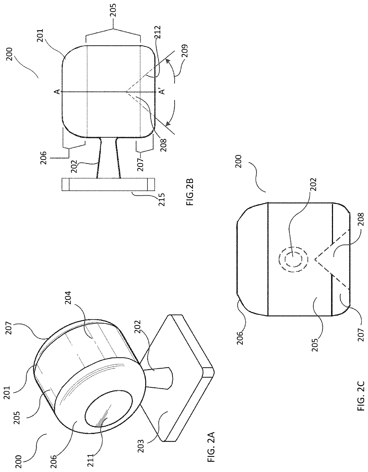
[0006]A machinable preform is described that is shapeable into a dental restoration with sufficient strength for anterior or posterior applications without the need for a further processing step to strengthen the dental restoration after it has been shaped. A sintered preform may be shaped into a colored final, custom dental restoration. The sintered preform comprises a body of sintered material and a stem projecting from the center of the preform body. Using a chair-side machine, a dental restoration may be shaped from the sintered preform, requiring no sintering after shaping, significantly reducing the time to create a custom finished product. The sintered preform has a unique size and shape that accommodates most custom restoration designs, and reduces the amount of sintered material to be removed during shaping a dental restoration. Advantageously, the placement of the stem facilitates a unique tool path and machining strategy for shaping dental restorations from sintered materials with no further sintering after shaping a dental restoration.
[0007]A method for making a sintered preform is also disclosed that comprises the steps of obtaining unsintered material, shaping the unsintered material into an unsintered shaped form having a body and a stem, and sintering the shaped form to full density to form the sintered preform. Unsintered material obtained in the form of a single block may be milled into an unsintered, unitary continuous shaped form. Alternatively, unsintered material is molded by injection molding, into the unsintered shaped form. In another alternative, unsintered material is molded into an intermediate shaped form, and then milled for further shape refinement prior to sintering to a final shaped form. In one embodiment, a pre-sintered ceramic block is milled into an intermediate shaped form, and then sintered to full density to form the sintered preform which may be shaped by a chair-side mill into a finished dental restoration. Advantageously, the preform stem facilitates a unique tool path and machining strategy for shaping a dental restoration from the sintered body. A unique tool is also described for use in shaping the sintered preform into dental restorations.

Problems solved by technology

Disadvantageously, the separate steps of milling the porous ceramic dental design and sintering the milled shape to form the final restoration, may preclude dentists from making chair-side ceramic restorations, increasing the amount of time a patient must wait for repair.

Method used


Image

  • Dental restoration preform and method of making the same
  • Dental restoration preform and method of making the same
  • Dental restoration preform and method of making the same

Examples


examples 1-21

[0061]Twenty-one zirconia crowns of multiple tooth types (numbers) were shaped from sintered zirconia preforms by the methods described herein.

[0062]Pre-sintered zirconia milling blocks were obtained (BruxZir® Shaded milling blocks, Glidewell Direct, Irvine, Calif.) and milled into cylindrically shaped preforms. The preforms having a circular cross-section were milled by standard milling procedures incorporating an enlargement factor calculated from the block density. The intermediate pre-sintered shaped forms had a cylindrical body, with a top and bottom end, a stem having a first stem end equidistance from the top and bottom ends, the stem extended orthogonally from the center portion relative to the length of the cylindrical body, an attaching member attached to a second stem end, substantially as depicted in FIG. 1A. The preforms had a cavity extending inwardly from a bottom end face. The stem had sufficient length between the attaching member and the cylindrical body for positi...

examples 22-25

[0068]Zirconia crowns were shaped from sintered zirconia preforms that were made substantially according to the methods provided in Examples 1-21.

[0069]A restoration design was created for a second molar (tooth number 15) using a dental CAD system (IOS™ FASTDESIGN) based on patient scan data. The restoration design was nested within a computer model of a preform. The size and shape of the preform provided full rotation of the restoration design around the z-z′ axis providing alternate locations on the crown restoration design for positioning the preform stem. The restoration design was nested four times to provide four nested designs, and in each nesting operation, the stem of the preform was positioned in one of four different locations, as indicated in Table 2. Nesting positions included placement of the Y-axis of the stem between mesial contact area and buccal surfaces (mesio-buccal), between distal contact area and buccal surfaces (disto-buccal), between distal contact area and ...


PUM

PropertyMeasurementUnit
widthaaaaaaaaaa
diameteraaaaaaaaaa
diameteraaaaaaaaaa

Abstract

A machinable preform for shaping into dental restorations is described that comprises material having suitable strength for use in dental applications without requiring further processing after shaping to strengthen the material (such as sintering). In one embodiment, a preform is comprised of a machinable dental material having a Vickers hardness value in the range of 4HV GPa to 20HV GPa, and comprises a body and a stem that extends from the outer surface of the body that supports the body during shaping. A method for making the machinable preform, and a kit comprising a machinable preform and a grinding tool, are also described.

Description

CROSS-REFERENCE TO RELATED APPLICATION[0001]This application claims the benefit of and priority to U.S. Provisional Patent Application No. 62 / 200,532, filed on Aug. 3, 2015, the entirety of which application is incorporated herein by reference.BACKGROUND OF THE INVENTION[0002]Ceramic materials known for use in the field of dentistry provide high strength restorations such as crowns, bridges, and the like. Some ceramic materials have flexural strength values exceeding 800 MPa when fully sintered, resulting in restorations that are resistant to chipping, breakage and wear. Material advances provide enhanced aesthetics in color and translucency while maintaining acceptable strength, and restorations may be manufactured from these materials in a cost effective manner.[0003]Dental restorations created by computer assisted design processes may be milled by CAM processes from porous ceramic materials in the green or pre-sintered ceramic stage, using an enlargement factor to accommodate red...

Claims


Application Information

Patent Timeline
Patent Type & Authority Patents(United States)
IPC IPC(8): A61C13/00C04B35/64B28B11/08A61C13/083C04B35/48A61C5/77A61C13/12
CPCA61C13/0022A61C13/083B28B11/08C04B35/48C04B35/64A61C5/77A61C13/12
Inventor LEESON, DAVID CHRISTOPHERJOKADA, MARCO A.NEMAGRDI, VAHEH GOLESTANIANMADANIPOUR, HOSSEIN
Owner JAMES R GLIDEWELL DENTAL CERAMICS
Why Eureka
Eureka Blog
Learn More