Supercharge Your Innovation With Domain-Expert AI Agents!

Imprint apparatus and method of manufacturing article

a technology of imprint apparatus and manufacturing method, which is applied in the direction of photomechanical treatment, instruments, optics, etc., can solve the problems of excessive or deficient imprint material, defect in the pattern formed on the substrate, and the formation of defect patterns. to achieve the effect of reducing the generation of defects

Active Publication Date: 2021-07-06
CANON KK
View PDF16 Cites 0 Cited by
  • Summary
  • Abstract
  • Description
  • Claims
  • Application Information

AI Technical Summary

Benefits of technology

The solution effectively reduces defects caused by excess or deficiency of imprint material, ensuring consistent and accurate pattern formation on the substrate by dynamically adjusting the material amount during the imprint process.

Problems solved by technology

If the mold is brought into contact with the imprint material in a state in which the amount of the imprint material on the substrate does not satisfy an appropriate amount due to the evaporation of the imprint material, a defective pattern may be formed on the substrate.
Even when the imprint material is arranged with consideration to the evaporation of the imprint material, if the time taken from the arrangement of the imprint material onto the substrate until the contact with the mold falls outside a predetermined range of time, the imprint material can become excessive or deficient.
This can create a defect in the pattern formed on the substrate.
Alternatively, the imprint material may also become excessive or deficient in a case in which the information for controlling the supplying of the imprint material onto the substrate is set incorrectly.

Method used


Image

  • Imprint apparatus and method of manufacturing article
  • Imprint apparatus and method of manufacturing article
  • Imprint apparatus and method of manufacturing article

Examples


first embodiment

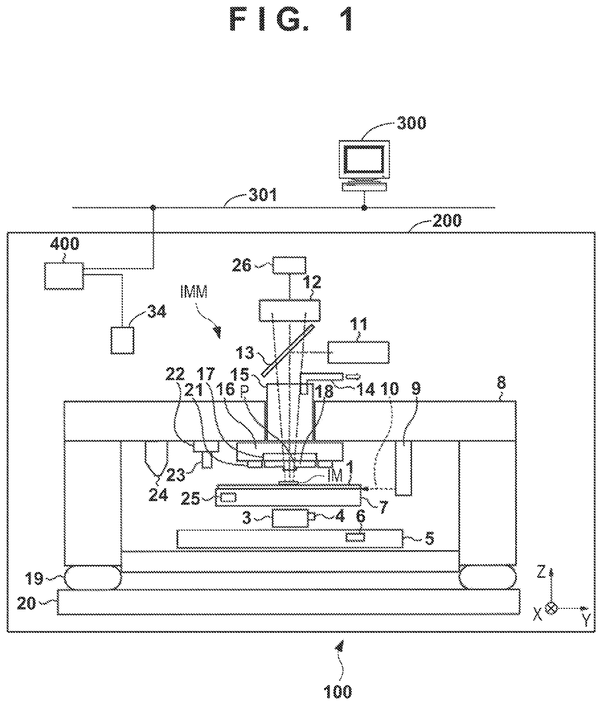
[0059]FIGS. 9A, 9B, and 10 show an operation example of the imprint apparatus 100 according to the The operation according to the operation example is controlled by the controller 400. In step S100, the alignment of the mold 18 and the substrate stage 7 is performed based on the result of the alignment measurement by the alignment measurement device 12. At this time, the mold 18 is loaded into the imprint apparatus 100 by a conveyance system (not shown), transferred to the mold chuck 17, and held by the mold chuck 17. Each mark (alignment mark) to be detected by the alignment measurement device 12 may be provided as a dedicated reference mark on the substrate stage 7 or may be provided on a dedicated alignment substrate.

[0060]In step S101, a predetermined elapsed time, from the arrangement of the imprint material until the mold 18 is brought into contact with the imprint material, is calculated by the first calculator 4031 of the time calculator 403 based on the following informati...

case 6

[0130]In Case 6, after the completion of the imprint process on the shot region of shot number 7, the imprint material is additionally supplied to the shot regions of shot numbers 6 (B), 8 (D), 9 (E), and 10 (F), and the imprint process is executed in accordance with this order. Time t13 is required to additionally supply the imprint material to the shot regions of shot numbers 6 (B), 8 (D), 9 (E), and 10 (F).

[0131]As described with respect to Case 2, in a case in which the pre-contact alignment measurement operation for a given shot region has failed, the result from the pre-contact alignment measurement operation that has been already executed for a shot region adjacent to the given shot region can be used. However, there may be a case in which the pre-contact alignment measurement operation for a given shot region has failed but the pre-contact alignment measurement operation has not yet been performed for the shot region adjacent to the given shot region. In such a case, it is p...


PUM

PropertyMeasurementUnit
wavelengthaaaaaaaaaa
timeaaaaaaaaaa
volatilityaaaaaaaaaa

Abstract

An imprint apparatus performs an imprint process by bringing a mold into contact with an imprint material arranged on a shot region of a substrate and curing the imprint material. The apparatus includes a controller configured to execute, in a case where an elapsed time from the supplying of the imprint material to the shot region until the contact with the mold falls outside an allowable range of a predetermined elapsed time, adjustment processing of adjusting an amount of the imprint material on the shot region at the timing of the contact.

Description

BACKGROUND OF THE INVENTIONField of the Invention[0001]The present invention relates to an imprint apparatus and a method of manufacturing an article.Description of the Related Art[0002]An imprint technique is a technique of forming, on a substrate, a pattern made from a cured imprint material by arranging the imprint material on the substrate and curing the imprint material upon bringing a mold into contact with the imprint material. Since the imprint material has volatility, the amount of the imprint material can decrease during the period in which the imprint material is arranged on the substrate until the mold is brought into contact with the imprint material. If the mold is brought into contact with the imprint material in a state in which the amount of the imprint material on the substrate does not satisfy an appropriate amount due to the evaporation of the imprint material, a defective pattern may be formed on the substrate.[0003]Japanese Patent Laid-Open No. 2009-532906 disc...

Claims


Application Information

Patent Timeline
Patent Type & Authority Patents(United States)
IPC IPC(8): G03F7/00B29C35/08B29C59/02
CPCG03F7/0002B29C35/08B29C59/02B29C2035/0827B29C59/002B29C2037/90
Inventor HIRANO, SHINICHI
Owner CANON KK
Features
  • R&D
  • Intellectual Property
  • Life Sciences
  • Materials
  • Tech Scout
  • Unparalleled Data Quality
  • Higher Quality Content
  • 60% Fewer Hallucinations
Learn More