
Gas arrester

a gas arrester and gas technology, applied in the field of gas arresters, can solve the problems of data lines, large challenge to the manufacturers of protection elements, complex voltage and overcurrent, etc., and achieve the effect of reliable gas arrester

Active Publication Date: 2021-07-13
EPCOS AG
View PDF15 Cites 1 Cited by
  • Summary
  • Abstract
  • Description
  • Claims
  • Application Information

AI Technical Summary

Benefits of technology

[0008]Embodiments provide an improved gas arrester, for example, a gas arrester that is particularly simple, space-saving and / or economical, and / or that particularly effectively protects data line systems with more than two lines against over-voltages. A further object consists in indicating the use of an improved gas arrester.
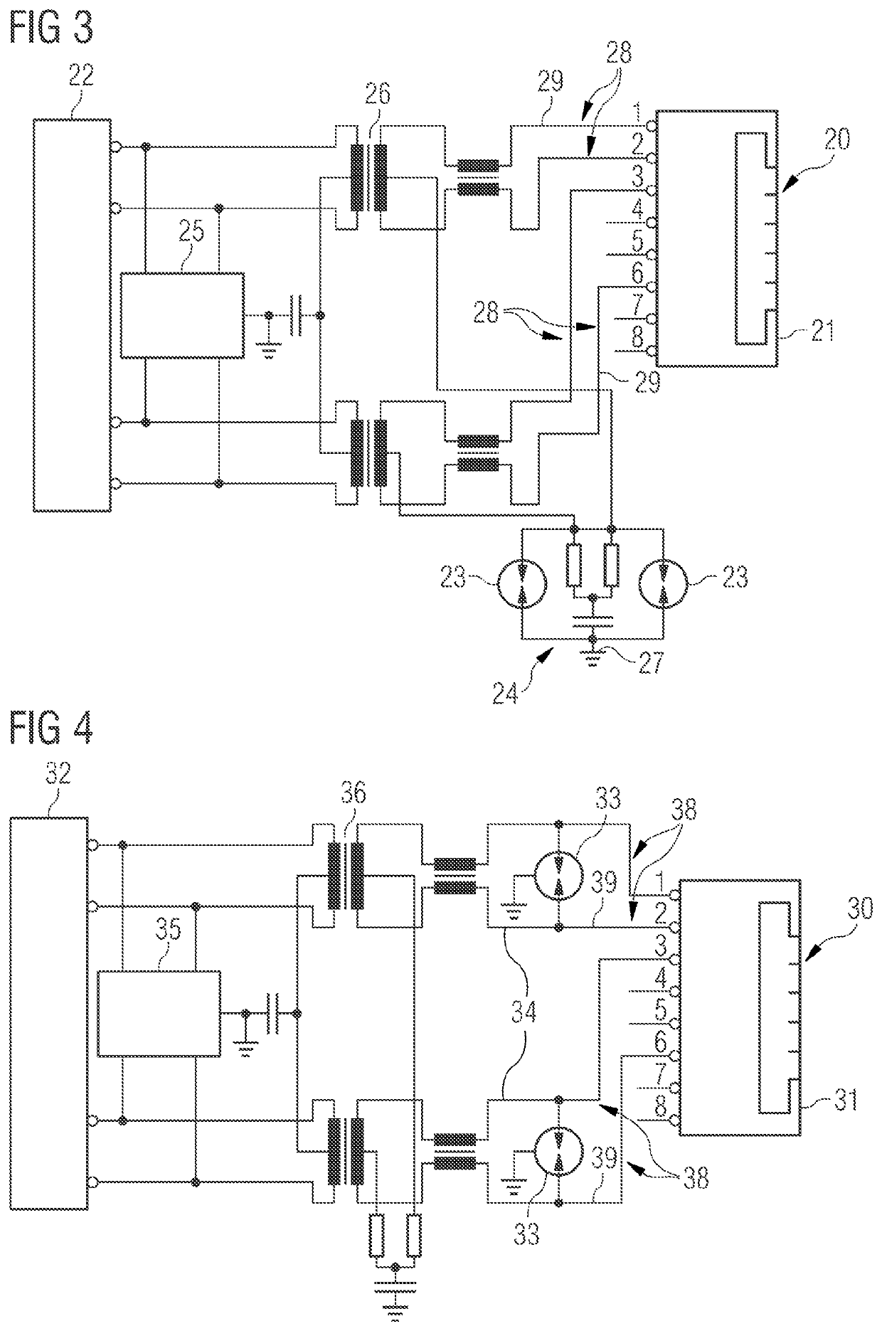
[0013]Due to the large number of individual electrodes, a plurality of cores or core pairs of the data line system can be protected with respect to ground. One individual electrode is provided here for each conductor of a pair. The discharge electrode is at ground potential. Data line systems with >>2 lines can thereby effectively be protected from over-voltages.
[0015]It is ensured in this way that when one path fires (arc discharge between an individual electrode and the discharge electrode), charge carriers are quickly emitted which lead to the firing of the respective neighboring path and finally to full firing. Voltage differences between cores or core pairs that could lead to destruction of the assembly are thus effectively avoided. A particularly effective gas arrester for the protection of data line systems is thus provided. The gas arrester is, furthermore, also very compact. Space can thus be saved on the circuit board. Very economical circuit boards can be built in this way.
[0016]According to an embodiment, the gas arrester comprises a ceramic body. The ceramic body can be of angular design, for example, rectangular, or round, for example, cylindrical. The ceramic body comprises, for example, Al2O3. The individual electrodes are introduced at least partially into the ceramic body. The individual electrodes have, for example, a cylindrical or rectangular partial region. This partial region is preferably at least partially surrounded by the ceramic body. The ceramic body is designed for the electrical isolation of the individual electrodes. It is thus ensured that no electrically conductive connection can be formed between the individual electrodes. A particularly reliable gas arrester is thus provided.
[0020]According to an embodiment, the ceramic body comprises a plurality of chambers. Preferably a number of the chambers correspond to a number of individual electrodes. The ceramic body comprises, for example, four or eight chambers. The chambers are formed as openings. In other words, the chambers fully penetrate through the ceramic body, for example, in a horizontal direction. The chambers are designed for at least partial inclusion of the individual electrodes. The individual electrodes are effectively spatially separated from each other in this way. The development of a conductive connection between the individual electrodes is effectively prevented.
[0022]The respective separating wall comprises an incision or a notch. The incision can, for example, be formed by milling out the separating wall. The incision can have a round or angular form. The respective incision extends in the horizontal direction over the full extent of the separating wall. The respective incision is designed and arranged to enable an exchange of gas between the chambers. A common gas discharge region is thus made available between the individual electrodes and the discharge electrode in a simple and effective manner.

Problems solved by technology

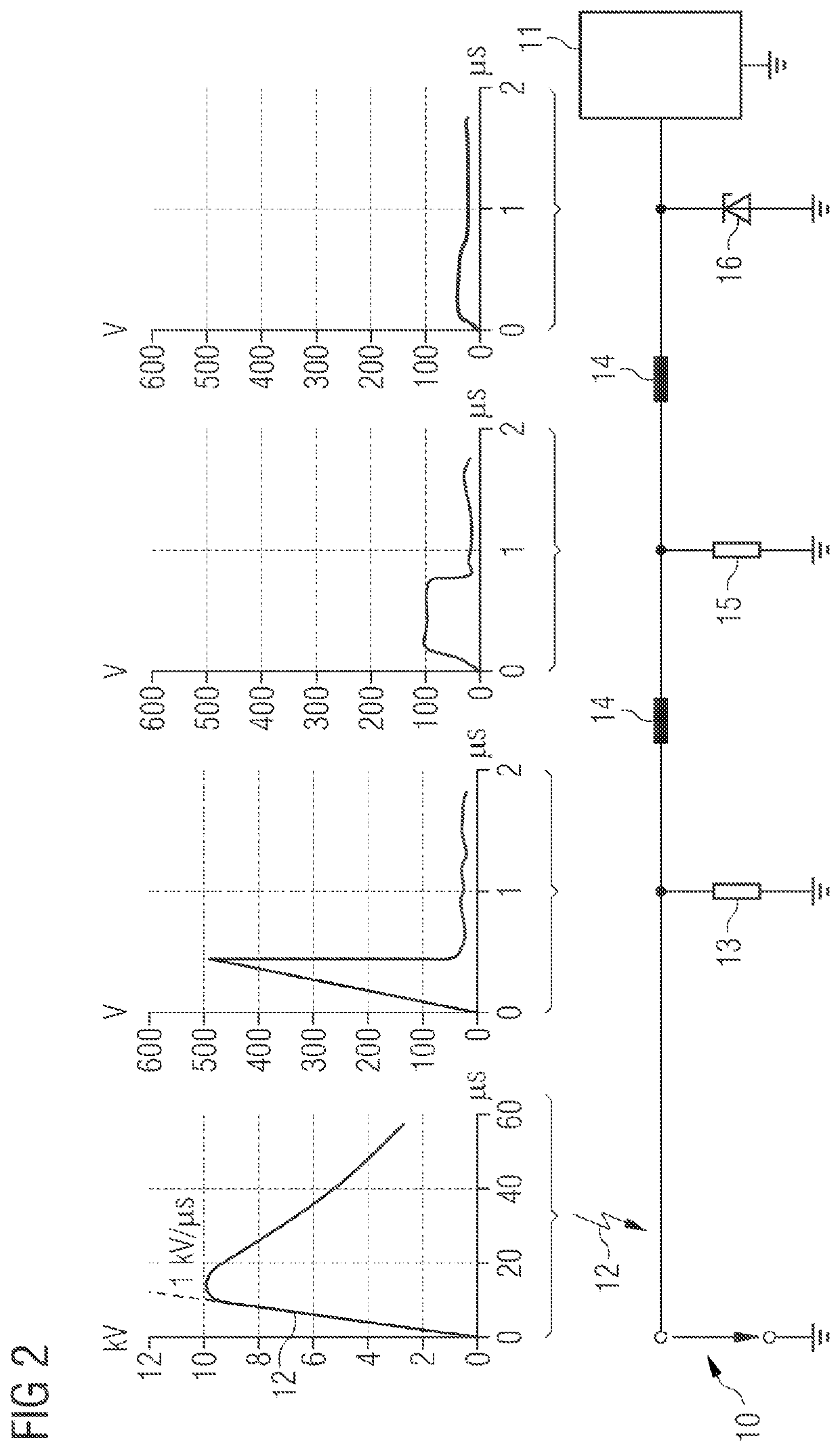
The protection of data lines in telecommunications applications against over-voltages and over-currents presents a major challenge to manufacturers of protection elements.
The assembly resulting from this for the protection against over-voltages and over-currents is thus complex and very voluminous.
In the case of data lines with more than two cores, this necessarily results in a high space requirement (one protection element per core).
Until now, the problem with data line systems with significantly more than two lines has not been satisfactorily solved.
However, these can only limit voltage differences between neighboring line cores.
Excessively high voltage differences that can destroy the assembly can arise between core pairs.

Method used


Image

  • Gas arrester
  • Gas arrester
  • Gas arrester

Examples


Embodiment Construction

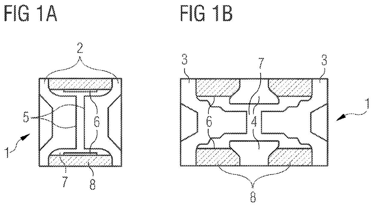
[0034]FIGS. 1a and 1b show conventional arresters 1 for protection against over-voltages. There are fundamentally two kinds of gas-filled arresters 1: two-electrode arresters (FIG. 1a) and three-electrode arresters (FIG. 1b).

[0035]The two-electrode arrester 1 shown in FIG. 1a comprises a first electrode and a second electrode 2, as well as a ceramic body 8 for isolation. The arrester 1 comprises a discharge region 7 to enable an electrical discharge between the electrodes 2 in the presence of an over-voltage. In the presence of an over-voltage, a discharge, in particular an arc discharge, should take place in the discharge region 7 between the electrodes 2. The discharge region 7 can be filled with a gas, in particular a noble gas.

[0036]An ignition aid 6 (for example, made of graphite) is provided in the discharge region 7 at an inner face of the ceramic body 8, and assists the development of a discharge when the arrester 1 is triggered. An activation material 5, for example, silica...


PUM


Abstract

A gas arrester is disclosed. In an embodiment a gas arrester for data line systems includes a discharge electrode, a plurality of individual electrodes for connection to data lines and a common gas discharge region formed between the individual electrodes and the discharge electrode.

Description

[0001]This patent application is a national phase filing under section 371 of PCT / EP2017 / 063840, filed Jun. 7, 2017, which claims the priority of German patent application 102016116148.9, filed Aug. 30, 2016, each of which is incorporated herein by reference in its entirety.TECHNICAL FIELD[0002]The invention relates to a gas arrester, in particular to a gas arrester for data line systems. The invention further relates to the use of a gas arrester.BACKGROUND[0003]The protection of data lines in telecommunications applications against over-voltages and over-currents presents a major challenge to manufacturers of protection elements. The protection elements must, on the one hand, limit the voltage promptly and must be able to withstand high lightning currents. On the other hand, the capacitance of the protection elements must be as low as possible, in order not to affect the transmitted signal.[0004]A so-called graded protection is integrated for this purpose in the majority of applica...

Claims


Application Information

Patent Timeline
Patent Type & Authority Patents(United States)
IPC IPC(8): H01T4/12H01T4/04H02H9/06H01T4/08H01T1/22H01T2/02G06F1/00H02H3/22
CPCH01T4/12H01T4/04H01T4/08H02H9/06G06F1/00H01T1/22H01T2/02H02H3/22
Inventor HOFFMANN, ROBERT
Owner EPCOS AG
Learn More