Apparatus and system configured to correct a cathode current and a voltage between a cathode and an anode for generating X-rays

a cathode and current correction technology, applied in the field of apparatus for generating x-rays, can solve the problems of reducing the x-ray output of the tube, exacerbating the deterioration of the anode, and reducing the x-ray flux with tube aging

Active Publication Date: 2021-07-13
KONINKLJIJKE PHILIPS NV
View PDF63 Cites 1 Cited by
  • Summary
  • Abstract
  • Description
  • Claims
  • Application Information

AI Technical Summary

Benefits of technology

[0012]In other words, it is known that X-ray emission changes with surface roughness of an anode, where the surface of an anode deteriorates through use, and using a correlation between surface anode roughness and backscatter electron emission an appropriate adjustment of the X-ray tube current can be made in order to maintain the X-ray emission at an optimum level on the basis of a measured backscatter electron signal. This means not only can the apparatus auto-correct the X-ray flux through appropriate correction of the X-ray tube current and / or a correction to the voltage between the cathode and the anode, remedial work by field service engineers does not have to be initiated as frequently, thereby saving costs.
[0013]Constant monitoring can help predict remaining lifetime of tube thus help in predictive maintenance, system uptime and better service contracts.
[0018]In other words, an X-ray pinhole camera is used to determine characteristics of the electron beam focused on the anode on the basis of direct electron detection. Thus high signals are obtainable, with high spatial resolution and dynamic range. Knowing the characteristics of the electron focal spot appropriate feed-back loops maintaining that focal spot in an optimum form can then be implemented.
[0022]In this way, because the location and size of the electron focal spot can be held at the correct position, the size of the electron beam focal spot can be maximized for a particular application. This means that X-ray fluxes can be maximized for a particular electron power density on the anode, because the focal spot does not need to be smaller than the optimum due to beam wander and focal spot size variation.
[0034]In this manner, because the size and / or location the electron focal spot can determined a correction can be made to maximize the size of the focused electron beam and / or more correctly locate the focused electron beam. This means that X-ray fluxes can be maximized for a particular electron power density on the anode, because the focal spot does not need to be smaller than the optimum due to beam wander and / or focal spot size variation. Furthermore, for a required X-ray flux the electron power density can be reduced providing for longevity of the anode, and / or gantry rotational rates can be reduced leading to a reduction in mechanical friction loss in hydrodynamic bearings.

Problems solved by technology

Anode target deterioration is one of the causes of tube aging especially for Computer Tomography (CT) tubes, leading to decrease in X-ray flux with tube aging.
It is well known that the X-ray output of a tube decreases with usage due to roughening of the surface of the X-ray emitting area of the anode target, which causes self-filtration.
Therefore in light of such issues, to maintain maximum X-ray flux, the power delivered the anode must be increased thereby exacerbating deterioration of the anode, or increase mechanical friction loss in hydrodynamic bearings due to a required increase in rotational speed of the anode.

Method used


Image

  • Apparatus and system configured to correct a cathode current and a voltage between a cathode and an anode for generating X-rays
  • Apparatus and system configured to correct a cathode current and a voltage between a cathode and an anode for generating X-rays
  • Apparatus and system configured to correct a cathode current and a voltage between a cathode and an anode for generating X-rays

Examples


Embodiment Construction

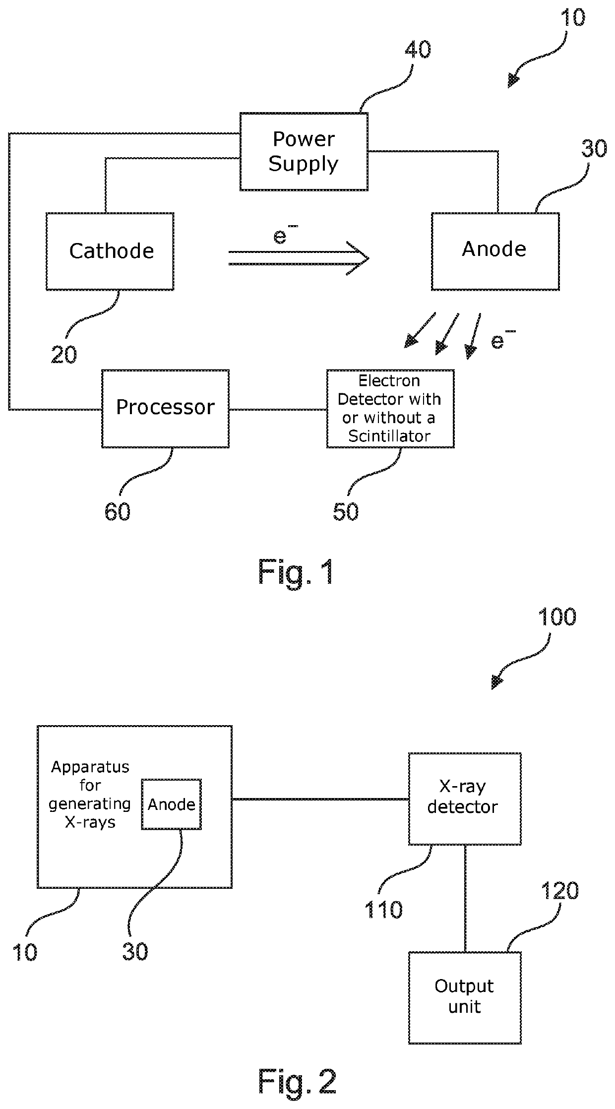
[0059]FIG. 1 shows an example of an apparatus 10 for generating X-rays. The apparatus 10 comprises a cathode 20, an anode 30, at least one power supply 40, an electron detector 50 and a processing unit 60. The at least one power supply 40 is configured to produce a voltage between the cathode 20 and the anode 30. The at least one power supply 40 is configured to provide the cathode 20 with a cathode current. The cathode 20 is positioned relative to the anode 30, and the cathode 20 and anode 30 are operable such that electrons emitted from the cathode 20 interact with the anode 30 with energies corresponding to the voltage. The electrons interact with the anode 30 at a focal spot to generate X-rays. The electron detector 50 is positioned relative to the anode 30, and is configured to measure a backscatter electron signal from the anode 30. The electron detector 50 is configured to provide the measured backscatter electron signal to the processing unit 60. This is via a wired or wirel...


PUM


Abstract

At least one power supply produces a voltage between a cathode and an anode. The cathode and anode are operable such that electrons emitted from the cathode interact with the anode with energies corresponding to the voltage. The electrons interact with the anode at a focal spot to generate X-rays. The power supply provides the cathode with a cathode current. An electron detector is positioned relative to the anode, and a backscatter electron signal is measured from the anode. The measured backscatter electron signal is provided to a processing unit, which determines a cathode current correction and / or a correction to the voltage between the cathode and the anode using the measured backscatter electron signal and a correlation between anode surface roughness and backscatter electron emission.

Description

FIELD OF THE INVENTION[0001]The present invention relates to an apparatus for generating X-rays, to a system for imaging an object, to a method for generating X-rays, as well as to a computer program element and a computer readable medium. The invention also relates to an apparatus and method for controlling a focused electron beam used in generating X-rays.BACKGROUND OF THE INVENTION[0002]The general background of this invention is the generation of X-rays. Anode target deterioration is one of the causes of tube aging especially for Computer Tomography (CT) tubes, leading to decrease in X-ray flux with tube aging. It is well known that the X-ray output of a tube decreases with usage due to roughening of the surface of the X-ray emitting area of the anode target, which causes self-filtration. The considerable effect of surface roughness and cracks on the reduction of x-ray output spectra (5-20% reduction in flux) is reported for example in: M. Erdélyi et al, Measurement of the x-ray...

Claims


Application Information

Patent Timeline
Patent Type & Authority Patents(United States)
IPC IPC(8): A61B6/00A61B6/03H01J35/06H01J35/08H01J35/14H05G1/02H05G1/08H05G1/10H05G1/26H05G1/32H05G1/34H05G1/46H05G1/52H05G1/54H01J35/10
CPCH05G1/52A61B6/032A61B6/40A61B6/405A61B6/4021A61B6/42A61B6/4208A61B6/4258A61B6/44A61B6/4429A61B6/4435A61B6/54A61B6/542A61B6/545A61B6/58A61B6/582H01J35/06H01J35/08H01J35/10H01J35/14H01J35/147H01J35/153H05G1/02H05G1/08H05G1/10H05G1/26H05G1/265H05G1/32H05G1/46H05G1/54H05G1/34H05G1/30
Inventor DOKANIA, ANAND KUMARBEHLING, ROLF KARL OTTO
Owner KONINKLJIJKE PHILIPS NV
Why Eureka
Try Eureka