Image forming apparatus with rotating guide member that guides sheet

a technology of rotating guide member and guiding sheet, which is applied in the direction of electrographic process apparatus, instruments, optics, etc., can solve the problems of expensive motors and motors, and achieve the effects of improving the productivity per unit time of sheets, low cost, and large base weigh

Active Publication Date: 2021-08-03
CANON KK
View PDF8 Cites 0 Cited by
  • Summary
  • Abstract
  • Description
  • Claims
  • Application Information

AI Technical Summary

Benefits of technology

[0010]Accordingly, the present invention aims to improve the productivity per unit time of sheets with a large basis weight at low cost.

Problems solved by technology

However, to make available an extra amount of force for switching the guide member regardless of the basis weight of the sheet, an expensive motor would be necessary, for example, as the driver that drives the guide member.

Method used


Image

  • Image forming apparatus with rotating guide member that guides sheet
  • Image forming apparatus with rotating guide member that guides sheet
  • Image forming apparatus with rotating guide member that guides sheet

Examples


embodiment 1

[0025]An image forming apparatus according to this embodiment will now be described. In this embodiment, a color image forming apparatus that uses an electrophotographic system is shown as one example of image forming apparatus. More specifically, the illustrated image forming apparatus is of an intermediate transfer tandem system in which photosensitive members of four colors are aligned on an intermediate transfer belt.

(Image Forming Apparatus)

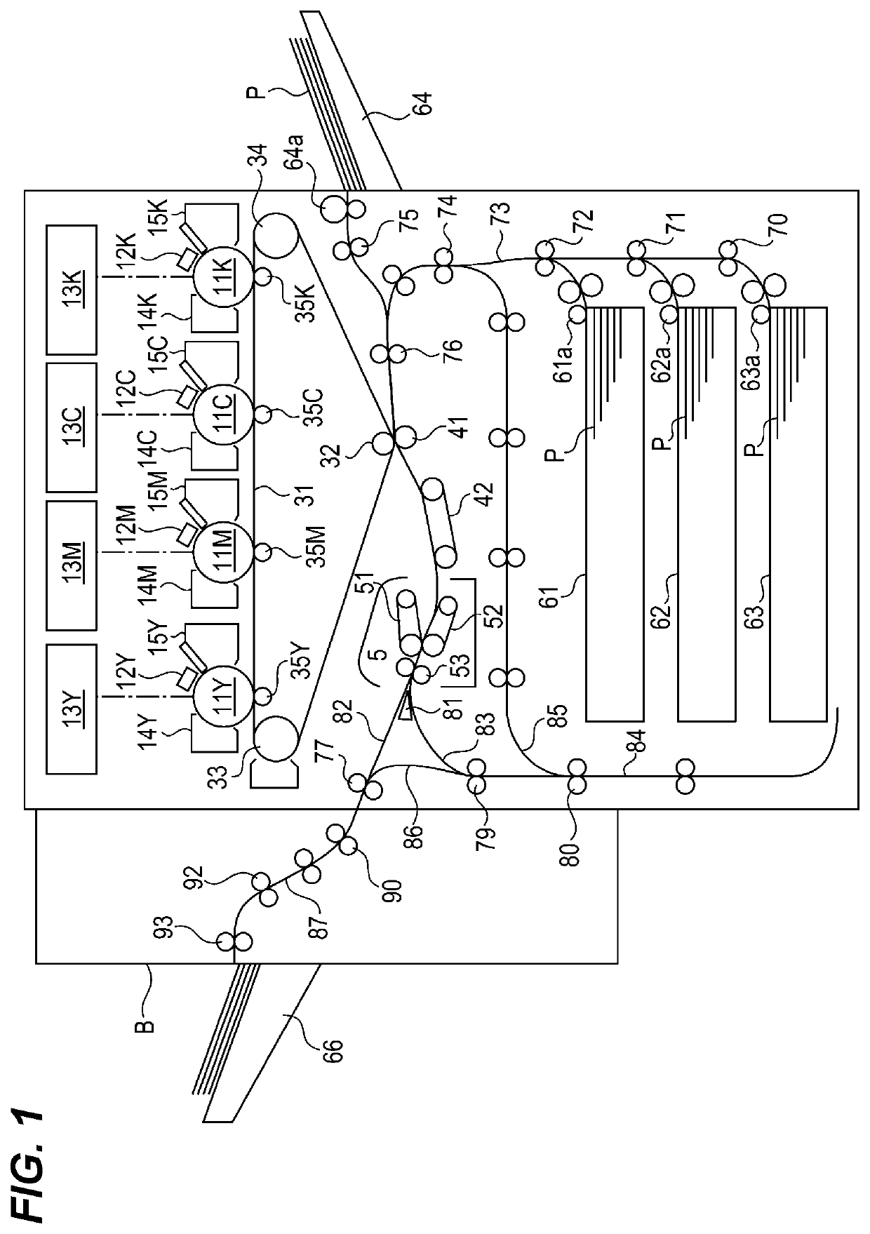
[0026]FIG. 1 shows a schematic cross-sectional view of the image forming apparatus according to this embodiment. The image forming apparatus according to this embodiment will be described with reference to FIG. 1.

[0027]Sheets P are stored in stack in sheet storage cases 61 to 64. The sheets P stored in the sheet storage cases 61 to 64 are selectively fed by sheet feeders 61a to 64a in sync with the image formation. A sheet P fed out by the sheet feeders 61a to 64a is passed through pairs of conveying rollers 70 to 75, a conveying path 73 and...

embodiment 2

[0081]In Embodiment 1, the speed and current settings of the drive motor for driving the guide member 81 are changed in accordance with the basis weight of the sheet selected by the user. In comparison to this, in this embodiment, as shown in FIG. 11, the speed and current settings of the drive motor for driving the guide member 81 are changed in accordance with not only the basis weight of the sheet but also a mode that prioritizes either image quality or productivity as selected by the user.

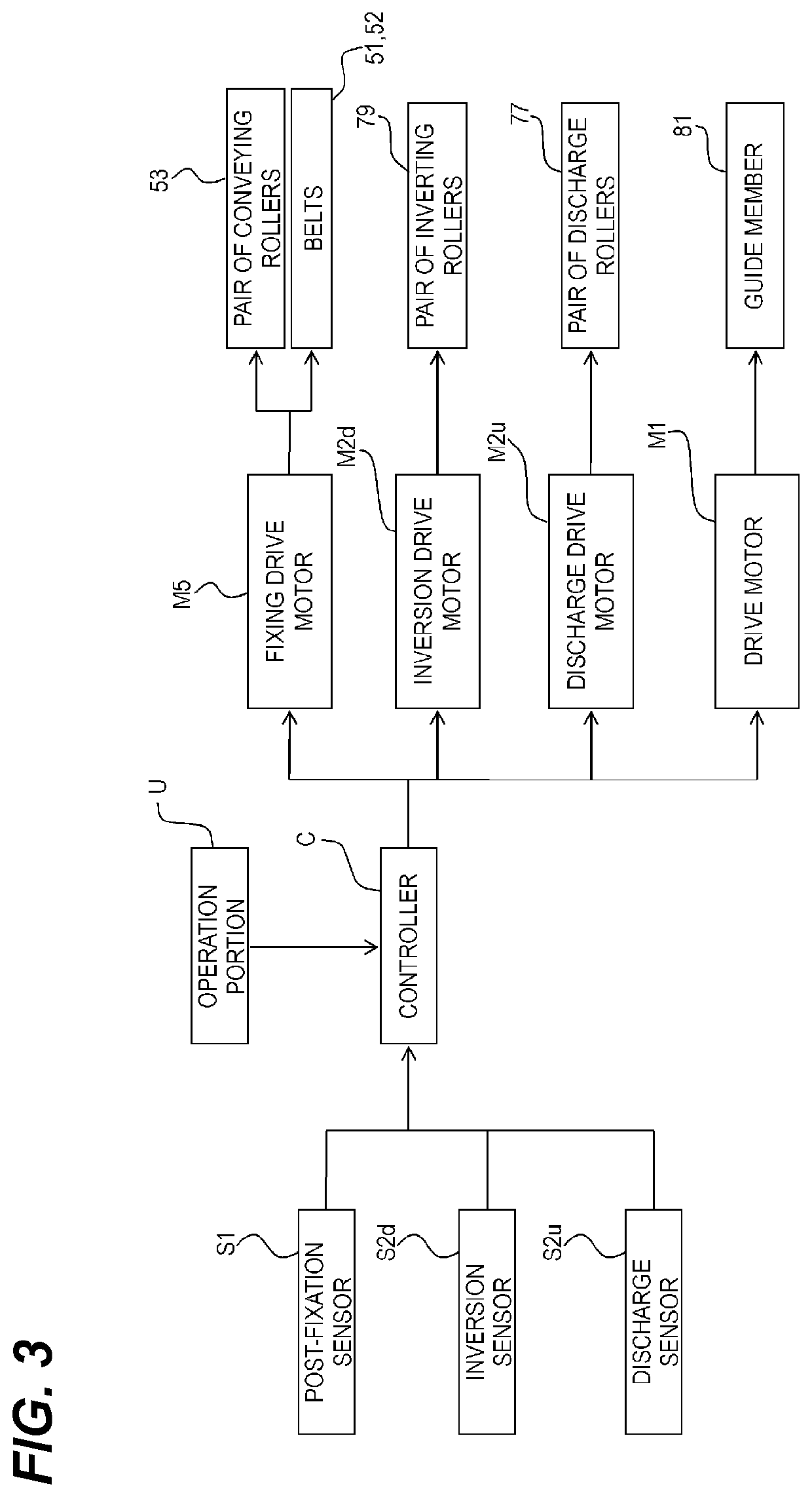
[0082]The operation portion U shown in FIG. 3 allows for setting of a mode that prioritizes either image quality or productivity. The controller C changes the rotation speed (switching speed) of the guide member 81 rotated by the drive motor M1 or the current to the drive motor M1 so as to change the torque for driving the guide member 81 in accordance with the set basis weight of the sheet and the priority mode.

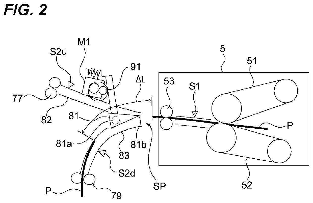
[0083]Referring to FIG. 11, the distance ΔL between sheets when the sheet is thick ...


PUM


Abstract

An image forming apparatus includes: a first conveying member that nips and conveys a sheet; a guide member rotatable between a first guiding position where the guide member guides a sheet that is conveyed by the first conveying member toward a first direction and a second guiding position where the guide member guides the sheet toward a second direction that is different from the first direction; a second conveying member that conveys a sheet that has been guided toward the first direction; a third conveying member that conveys a sheet that has been guided toward the second direction; a driver that drives the guide member; an acquiring portion configured to acquiring a basis weight of a sheet; and a controller that controls the driver such as to change torque for driving the guide member based on a basis weight of a sheet acquired by the acquiring portion.

Description

BACKGROUND OF THE INVENTIONField of the Invention[0001]The present invention relates to an image forming apparatus that forms an image on a sheet.Description of the Related Art[0002]In an image forming apparatus such as a printer, typically, an image forming portion includes an image bearing member that carries a toner image, a transfer portion that transfers the toner image carried on the image bearing member to a sheet, and a fixing portion that fixes the transferred toner image on the sheet. The image forming apparatus also includes a sheet conveying apparatus for discharging the sheet on which the toner image has been formed by the image forming portion, or for inverting such sheet to be conveyed back to the image forming portion, or for discharging the sheet after inverting it for page alignment.[0003]Such a sheet conveying apparatus includes a sheet discharge path for discharging the sheet, a reconveying path that diverges from the sheet discharge path for conveying the sheet ...

Claims


Application Information

Patent Timeline
Patent Type & Authority Patents(United States)
IPC IPC(8): G03G15/00G03G15/20G03G15/16
CPCG03G15/2028G03G15/5029G03G15/657G03G15/6573G03G15/1675G03G15/50
Inventor TAKAHASHI, HIROYUKI
Owner CANON KK
Why Eureka
Try Eureka