Eureka AIR delivers breakthrough ideas for toughest innovation challenges, trusted by R&D personnel around the world.

Method of manufacturing emitter, emitter, and focused ion beam apparatus

a technology of focused ion beam and manufacturing method, which is applied in the manufacture of electric discharge tubes, electric discharge tubes/lamp details, and discharge tubes/lamp details to achieve the effect of narrowing the radiation angle of the ion beam and high reproducibility

Active Publication Date: 2021-08-03
HITACHI HIGH TECH SCI CORP
View PDF3 Cites 0 Cited by
  • Summary
  • Abstract
  • Description
  • Claims
  • Application Information

AI Technical Summary

Benefits of technology

[0014]At least one embodiment of the present disclosure is devised in view of the above situation, and aims at providing an emitter and a method of manufacturing the emitter in which by rearranging the atoms through the treatment, the crystal structure of the front end of the emitter may be returned to its original state with high reproducibility, and the radiation angle of the ion beam may be narrowed.
[0024]According to the emitter and the method of manufacturing the emitter of the present invention, by rearranging the atoms through the treatment, the crystal structure of the front end of the emitter may be returned to its original state with high reproducibility, and the radiation angle of the ion beam may be narrowed.

Problems solved by technology

However, an emitter and a method of manufacturing the emitter, which is capable of narrowing the radiation angle of the ion beam while allowing a crystal structure at a front end of the emitter to return to its original state with high reproducibility, by rearranging atoms through a treatment, are not proposed in the related art.

Method used


Image

  • Method of manufacturing emitter, emitter, and focused ion beam apparatus
  • Method of manufacturing emitter, emitter, and focused ion beam apparatus
  • Method of manufacturing emitter, emitter, and focused ion beam apparatus

Examples


modified embodiment

[0117]FIG. 15 is a diagram which shows another example of the shape of the sharp portion processed by the electric field-induced gas etching in the present exemplary embodiment. By modifying a part of the above-described emitter manufacturing method, an emitter having a truncated cone terrace portion shown in FIG. 15 may be manufactured. The manufacturing method of the base portion is the same as that of the above example, the description is omitted.

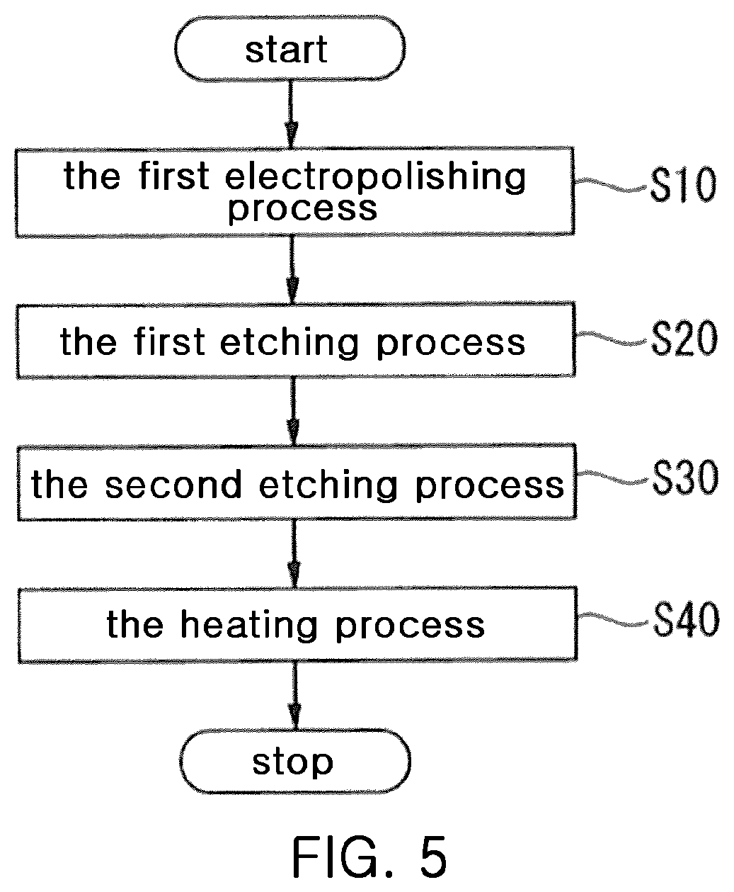
[0118]During the processing of the electric field-induced gas etching in the second etching process (Step S30), the high voltage applied to the emitter material 30 is maintained at fixed voltage.

[0119]By observation through the field ion microscope 50, the etching process is performed until the shape of the tip of the front end of the emitter material 30 becomes a predetermined shape. An example of the predetermined shape of this sharp portion 40 is the same as that of FIG. 13. The sharp portion 40 has the base portion BS and the terrace...


PUM

PropertyMeasurementUnit
vertex angleaaaaaaaaaa
diameteraaaaaaaaaa
voltageaaaaaaaaaa

Abstract

A method of manufacturing an emitter is disclosed. The method enables a crystal structure of the tip of the front end of the emitter to return to its original state with high reproducibility by rearranging atoms in a treatment, and enables a long lasting emitter to be attained by suppressing extraction voltage rise after the treatment. As a method of manufacturing an emitter having a sharpened needle-shape, the method includes: performing an electropolishing process for the front end of an emitter material having conductivity to taper toward the front end; and performing an etching to make the number of atoms constituting the tip of the front end be a predetermined number or less by further sharpening the front end through an electric field-induced gas etching having constantly applied voltage, while observing the crystal structure of the front end, by a field ion microscope, in a sharp portion having the front end at its apex.

Description

CROSS REFERENCE TO RELATED APPLICATION[0001]The present application claims priority to Japanese Patent Application No. 2019-057661, filed Mar. 26, 2019, the entire contents of which is incorporated herein for all purposes by this reference.BACKGROUND OF THE INVENTION1. Technical Field[0002]The present disclosure relates to a method of manufacturing an emitter, an emitter, and a focused ion beam apparatus.2. Description of the Related Art[0003]Conventionally, a focused ion beam apparatus is known as an apparatus for performing observations, various evaluations, and analyses of a sample such as a semiconductor device, or for manufacturing a TEM lamella by taking out a fine lamella from the sample and then fixing the lamella to a sample holder.[0004]This focused ion beam apparatus is provided with an ion source which generates ions, and then emits the generated ions as a focused ion beam (FIB).[0005]There are several kinds of ion sources. For example, a plasma ion source or a liquid me...

Claims


Application Information

Patent Timeline
Patent Type & Authority Patents(United States)
IPC IPC(8): H01J37/08H01J37/30H01J37/10H01J37/305
CPCH01J37/08H01J37/10H01J37/3053H01J2237/0807H01J2237/3174H01J2237/31749H01J9/02H01J27/26H01J37/28H01J1/304H01J9/025H01J37/147
Inventor KOZAKAI, TOMOKAZUKAWANAMI, YOSHIMIMUTOH, HIROYUKINAKAJIMA, YOKOMORITANI, HIRONORIMATSUBARA, SHINICHI
Owner HITACHI HIGH TECH SCI CORP
Why Eureka
Eureka Blog
Learn More