
Adjustable optical lens and camera module, manufacturing method and applications thereof

a technology of adjustment and optical lens, applied in the field of adjustable optical lens and camera module, can solve the problems of affecting the alignment of the central axis line of the lens and the central axis line of the optical sensor, affecting the application of the high-quality camera module for the market, and generating certain deviations between the central axis lines of each lens

Active Publication Date: 2021-08-24
NINGBO SUNNY OPOTECH CO LTD
View PDF14 Cites 1 Cited by
  • Summary
  • Abstract
  • Description
  • Claims
  • Application Information

AI Technical Summary

Benefits of technology

The adjustable optical lens system ensures accurate alignment of the central axis lines, enhancing image quality, increasing yield rates, and reducing production costs by simplifying the manufacturing process and reducing the need for extensive testing and calibration.

Problems solved by technology

However, due to the limitation of the molding and packaging technique of the camera module and the manufacturing process of the lens of the camera module, the current camera module in the market can barely fulfill the application needs of the high quality camera module for the market.
However, because of the limitation of the packaging technique, there is certain deviation generated among central axis lines of each lens.
In the process of packaging the lens and the optical sensor together to form the camera module, it is difficult to ensure that the central axis line of the lens and the central axis line of the optical sensor are aligned.
Once, there is a deviation between the central axis line of the lens and the central axis line of the optical sensor, the image quality of the camera module will certainly be affected.
Therefore, in the process of producing the camera module, how to ensure the image quality of the produced camera module and the series of problems being occurred as mentioned above while ensuring the image quality during production of the camera module become the major technical difficulties to be resolved.
Regular cellphone camera modules often have blur imaging issue due to tilt of the material or assembling.
Therefore, the assembling tolerance chain of this assembling method is too long, which brings high assembling cost and low accuracy of the assembling position of the lens and affects the quality of the camera lens.
As a result, the quality of the entire camera module and products installed with such camera module would be adversely influenced.

Method used


Image

  • Adjustable optical lens and camera module, manufacturing method and applications thereof
  • Adjustable optical lens and camera module, manufacturing method and applications thereof
  • Adjustable optical lens and camera module, manufacturing method and applications thereof

Examples


fifth embodiment

[0468]In the step (1704), solidifying the adhesive 1040D through a heating treatment fixedly attaches the first lens 10111D, the fifth lens 10115D and the aperture member 1014D to the optical structural member 1013D. Then, the adjustment channel 10131D is sealed. the sealing is conducted preferably by injecting adhesive into the adjustment channel 10131D, that seals and further fixes the first lens 10111D and the second lens 10112D in position, so as to package the adjustable optical lens 1010D and the photosensitive device 1020D.

[0469]Besides, in the step (1704), the present invention may has at least one adhesive injection channel 10141D provided in the aperture member 1014D for injecting adhesive (e.g. thermosetting adhesive) to further fixed the first lens 10111D and fifth lens 10115D after adjusted. Another implementation can have two adhesive injection channels 10141D that, after the first lens 10111D and the fifth lens 10115D are adjusted, thermosetting adhesive is injected ...

sixth embodiment

[0470]Referring to FIGS. 18-19, the camera module provided by the present invention will be illustrated. Referring to FIGS. 18-19, a camera module comprises an adjustable optical lens 2010 and an photosensitive device 2020, wherein the photosensitive device 2020 comprises an optical sensor 2021. The adjustable optical lens 2010 is arranged along a photosensitive path of the optical sensor 2021 that lights reflected from an object can enter an inside of the camera module through the adjustable optical lens 2010 and be received by the optical sensor 2021 to proceed photoelectric conversion, so that images respective to the object can be subsequently captured by the camera module.

[0471]The photosensitive device 2020 further comprises a filter 2022, a circuit board 2023, and a lens mount 2024. The filter 2022 is mounted in the lens mount 2024 and arranged above the optical sensor 2021. The optical sensor 2021 is attached on the circuit board 2023. The circuit board 2023 is mounted on a ...

seventh embodiment

[0483]Referring to FIGS. 21-22, the camera module provided by the present invention is illustrated. Referring to FIGS. 21-22, a camera module comprises an adjustable optical lens 2010B and a photosensitive device 2020, wherein the adjustable optical lens 2010B is arranged and affixed on top of the photosensitive device 2020 based on the imaging need and aligned in an optical path of the camera module, wherein the photosensitive device 2020 is embodied the same as the above preferred embodiments, which is not repeatedly described in this seventh preferred embodiment.

[0484]The adjustable optical lens 2010B comprises one or more lenses 2011B and an optical structural member 2013B. The lenses 2011B include a first lens 20111B, a second lens 20112B, a third lens 20113B, and a fourth lens 20114B, which are arranged in the internal space of the optical structural member 2013B sequentially along the vertical direction of the optical structural member 2013B and along the photosensitive path ...


PUM


Abstract

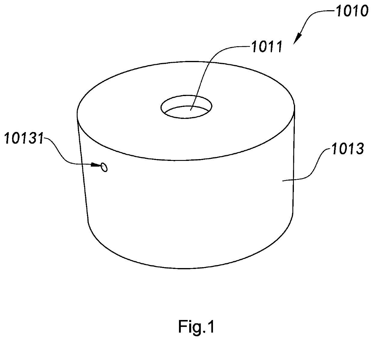
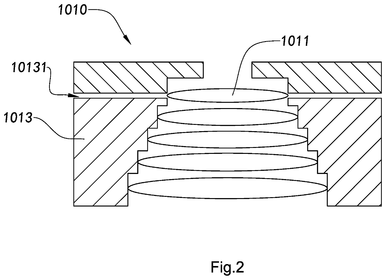
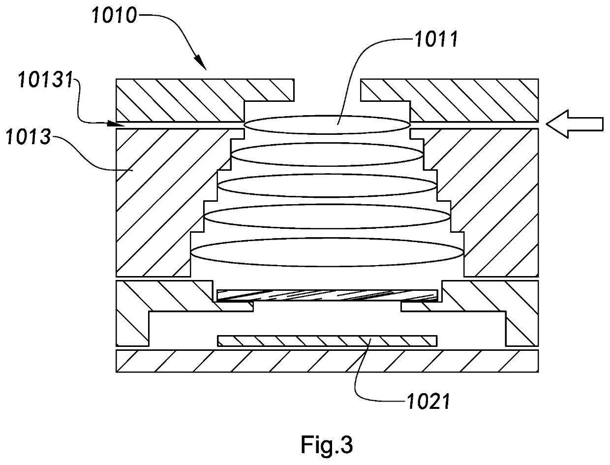
An adjustable optical lens and camera module, and manufacturing method and applications thereof is disclosed. The camera module includes an optical sensor and an adjustable optical lens. The adjustable optical lens includes an optical structural member and at least two lenses, wherein each of the lenses is arranged in an internal space of the optical structural member. Along a vertical direction of the optical structural member, at least one lens is adapted to be adjustably pre-mounted to an internal space of the optical structural member serving as an adjustable lens. The side wall of the optical structural member is provided with at least one adjustment channel, which is positioned corresponding to the adjustable lens, so that an assembling position of the adjustable lens can be adjusted through the adjustment channel so as to align a central axis line of the adjustable optical lens with a central axis line of the optical sensor.

Description

CROSS-REFERENCE TO RELATED APPLICATIONS[0001]This is a non-provisional application that claims the benefit of priority under 35U.S.C.§ 371 to international application number PCT / CN2016 / 103253, international filing date Oct. 25, 2016, which claims priority under 35 U.S.C. 119(a-d) to Chinese application number CN201510726575.6, filed Oct. 30, 2015, Chinese application number CN201510873537.3, filed Dec. 2, 2015, Chinese application number CN201510968893.3, filed Dec. 21, 2015 and Chinese application number CN201511009093.5, filed Dec. 29, 2015, which are incorporated herewith by references in their entities. wherein the entire contents of each of which are expressly incorporated herein by reference.NOTICE OF COPYRIGHT[0002]A portion of the disclosure of this patent document contains material which is subject to copyright protection. The copyright owner has no objection to any reproduction by anyone of the patent disclosure, as it appears in the United States Patent and Trademark Off...

Claims


Application Information

Patent Timeline
Patent Type & Authority Patents(United States)
IPC IPC(8): G02B7/10G02B5/20H04N5/225G02B7/02G02B7/00G02B13/00
CPCG02B7/10G02B5/20G02B7/00G02B7/003G02B7/02G02B7/023G02B7/025H04N5/2254G02B13/001H04N23/55
Inventor WANG, MINGZHUZHAO, BOJIEJIANG, HENGDING, LIANGCHEN, FEIFANLIU, CHUNMEIGUO, NANWANG, SHOUJIE
Owner NINGBO SUNNY OPOTECH CO LTD
Learn More