Dual input power supply with shortened switching

a power supply and switch technology, applied in the direction of dc-dc conversion, dc-ac conversion without reversal, emergency power supply arrangement, etc., can solve the problems electrical equipment may not operate normally, etc., and achieve the effect of shortening the power switching time of the power supply apparatus

Active Publication Date: 2021-08-24
MERRY ELECTRONICS (SHENZHEN) CO LTD
View PDF4 Cites 0 Cited by
  • Summary
  • Abstract
  • Description
  • Claims
  • Application Information

AI Technical Summary

Benefits of technology

[0005]In view of the above, the disclosure provides a power supply apparatus and a power supply method, which can shorten the power switching time of the power supply apparatus.
[0009]Based on the above, in the power supply apparatus and the power supply method proposed by the disclosure, before the control circuit enters the first mode, the power conversion circuit generates the boost voltage in advance according to the DC voltage of the DC power source. In this way, when the AC power source is abnormal, the control circuit only needs to turn off the first switching circuit and causes the power conversion circuit to convert the boost voltage to the backup AC voltage, and then the backup AC voltage can be output to the power supply terminal. Therefore, the switching time of the power supply source of the power supply terminal for switching from the AC power source to the DC power source can be shortened.

Problems solved by technology

However, when the main input power source is abnormal, if the switching time of the power supply source of the electrical equipment for switching from the main input power source to the backup input power source is too long, the electrical equipment may fail to operate normally due to temporary interruption of the power supply.
Therefore, how to shorten the power switching time of the power supply apparatus is one of the major issues that persons skilled in the art intend to solve.

Method used


Image

  • Dual input power supply with shortened switching
  • Dual input power supply with shortened switching
  • Dual input power supply with shortened switching

Examples


Embodiment Construction

[0018]In order to make the content of the disclosure easier to understand, embodiments are illustrated below as examples of the actual implementation of the disclosure. In addition, wherever possible, the drawings and the embodiments use elements / components / steps with the same reference numerals, which represent the same or similar parts.

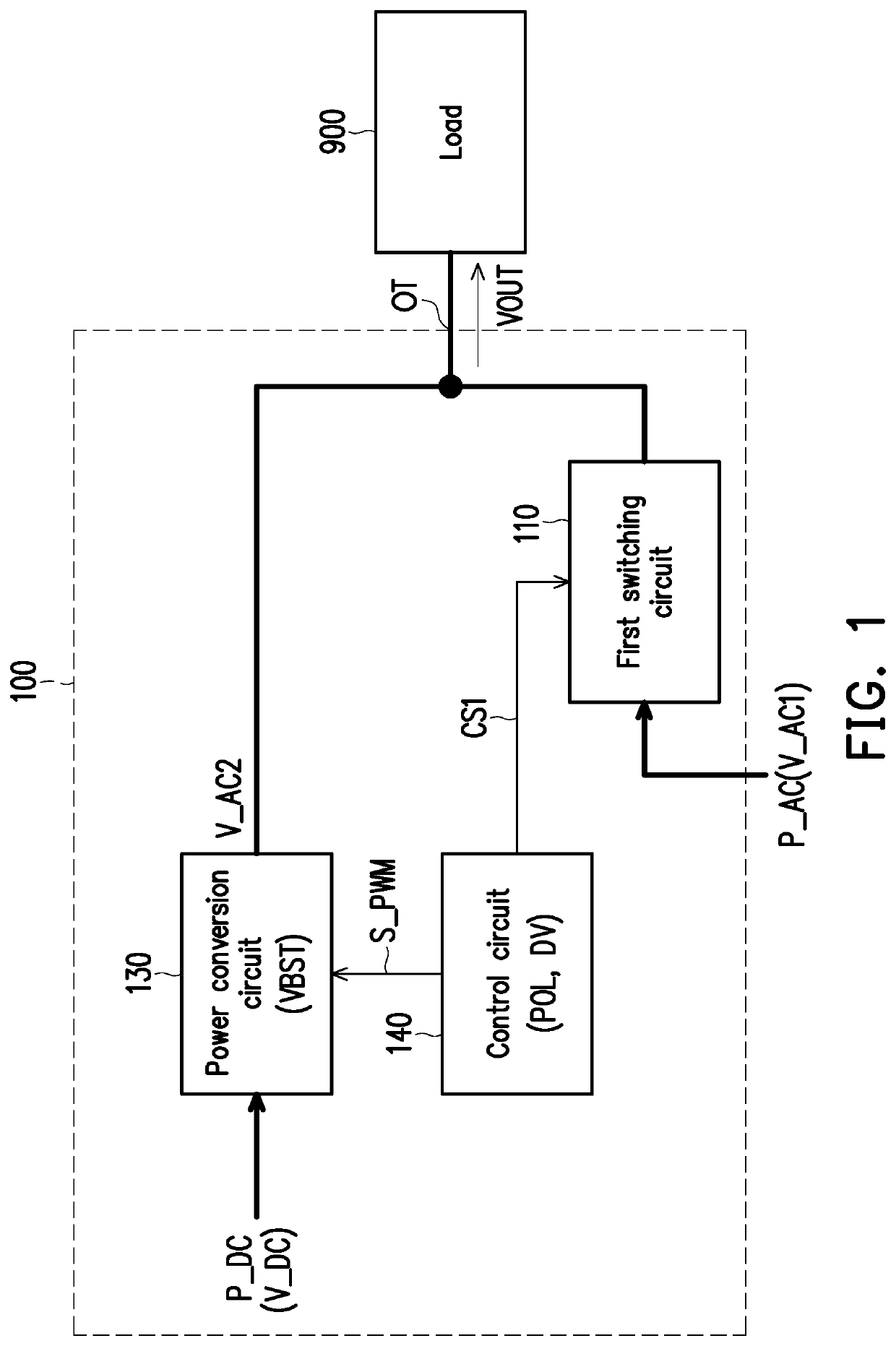
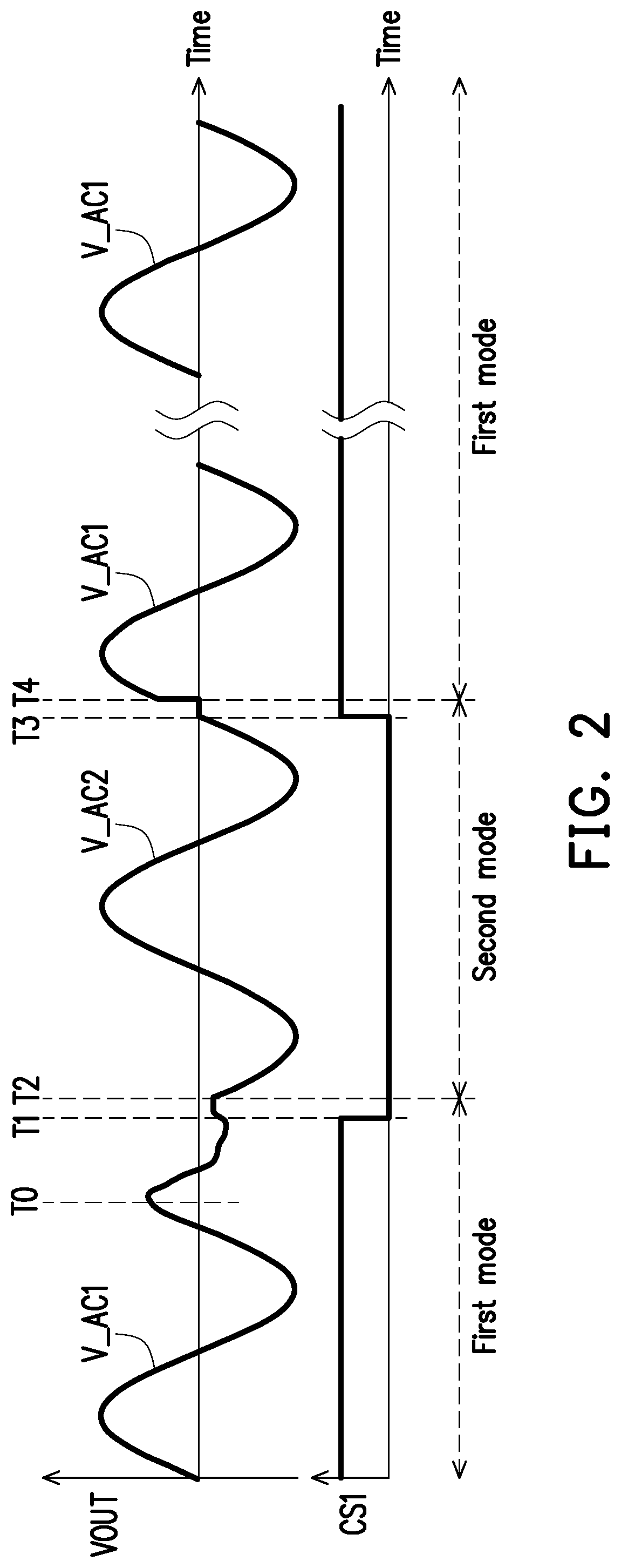
[0019]FIG. 1 is a schematic circuit block diagram of a power supply apparatus 100 according to an embodiment of the disclosure, and FIG. 2 is a schematic signal timing diagram of the power supply apparatus 100 according to an embodiment of the disclosure. With reference to FIG. 1 and FIG. 2 together, a power supply terminal OT of the power supply apparatus 100 is configured to be coupled to a load 900. The power supply apparatus 100 can provide an output voltage VOUT through the power supply terminal OT to supply power to the load 900. In detail, the power supply apparatus 100 may include a first switching circuit 110, a power conversion circuit 130...


PUM


Abstract

A power supply method and a power supply apparatus including a power conversion circuit, a first and a second switching circuit, and a control circuit are provided. The power conversion circuit is coupled between a DC power source and a power supply terminal and performs a boosting operation according to a DC voltage of the DC power source to generate a boost voltage. The first switching circuit is coupled between an AC power source and the power supply terminal. The second switching circuit is coupled between the power conversion circuit and the power supply terminal. The control circuit enters a first mode after turning on the first and the second switching circuit, so the first switching circuit transmits a main AC voltage of the AC power source to the power supply terminal in the first mode. The boost voltage is greater than a peak value of the main AC voltage.

Description

CROSS-REFERENCE TO RELATED APPLICATION[0001]This application claims the priority benefits of U.S. provisional application Ser. No. 62 / 796,592, filed on Jan. 25, 2019, and Taiwan application serial no. 108120098, filed on Jun. 11, 2019. The entirety of each of the above-mentioned patent applications is hereby incorporated by reference herein and made a part of this specification.BACKGROUNDTechnical Field[0002]The disclosure relates to a power supply technology, and more particularly to a power supply apparatus having a power source automatic switching function.Description of Related Art[0003]In order to ensure a stable operation of electrical equipment, a power supply apparatus with dual input power sources is usually used to supply power to the electrical equipment. A power supply apparatus with dual input power sources usually has an automatic transfer switch (ATS) that automatically switches the power supply source of the electrical equipment from the main input power source to th...

Claims


Application Information

Patent Timeline
Patent Type & Authority Patents(United States)
IPC IPC(8): H02J9/06H02M7/44
CPCH02J9/061H02M7/44H02J9/062H02M7/53871H02M1/36H02M3/156H02M1/007
Inventor LIU, YUNG-HSIANGLIANG, WEI-KANGWANG, YU-KAI
Owner MERRY ELECTRONICS (SHENZHEN) CO LTD
Why Eureka
Try Eureka