Blower fan having impeller and motor

a technology of blower fan and motor, which is applied in the direction of machines/engines, couplings, liquid fuel engines, etc., can solve the problems of vibration and noise, and generate large nois

Active Publication Date: 2021-09-07
RINNAI CORP
View PDF9 Cites 2 Cited by
  • Summary
  • Abstract
  • Description
  • Claims
  • Application Information

AI Technical Summary

Benefits of technology

[0010]Although the impeller may rotate with respect to the rotational shaft under a frictional force applied from the nut tightened to mount the impeller to the rotational shaft of the motor, the spacing portion of the mount hole is spaced from the locking surface to prevent the impeller at the mount hole from being pressed strongly against the locking surface of the rotational shaft and from causing metallic contact between them. This structure thus prevents the electromagnetic vibration of the motor from propagating to the impeller, and sufficiently reduces noise of the blower fan.
[0012]Shortening the distance between the spacing portion of the mount hole and the tangent to the arc portion parallel to the spacing portion accordingly extends the length of the linear portion of the mount hole. The nut tightened to mount the impeller having the mount hole with this shape (including the extended linear portion) to the rotational shaft can cause the extended linear portion of the mount hole to be pressed strongly against the locking surface (D-cut surface) of the rotational shaft and causes metallic contact between them when the impeller is urged to rotate with respect to the rotational shaft. In contrast, the distance between the spacing portion included in the mount hole and the tangent to the arc portion parallel to the spacing portion is greater than or equal to the distance between the linear portion and the tangent to the arc portion parallel to the linear portion to prevent the linear portion of the mount hole from being pressed strongly against the locking surface (D-cut surface) of the rotational shaft and from causing metallic contact between them when the impeller is urged to rotate with respect to the rotational shaft. This structure prevents noise resulting from the electromagnetic vibration of the motor.
[0014]The insertion holes of the rubber washers each include a linear portion in addition to the arc portion. The rubber washers can thus be positioned with respect to the rotational shaft in the rotation direction. The locking unit that locks rotation of the impeller with respect to the rubber washers can also position the impeller with respect to the rotational shaft in the rotation direction. This structure prevents instability in the positional relationship between the spacing portion of the mount hole and the locking surface of the rotational shaft when the rotational shaft is placed through the impeller and the rubber washers. Although the impeller rotates with respect to the rotational shaft under a frictional force applied from the nut tightened, this structure prevents the spacing portion of the mount hole from being pressed strongly against the locking surface of the rotational shaft.
[0016]In this manner, the locking unit can be formed easily. When the nut is tightened, this structure prevents the spacing portion of the mount hole from being pressed strongly against the locking surface of the rotational shaft.

Problems solved by technology

An impeller of a blower fan can be decentered from a rotational shaft of a motor and cause vibration and noise, and thus is to be centered when mounted on the rotational shaft of the motor.
In this blower fan, high-frequency vibration called electromagnetic vibration of the motor can propagate from the rotational shaft of the motor to the impeller and generate large noise.

Method used


Image

  • Blower fan having impeller and motor
  • Blower fan having impeller and motor
  • Blower fan having impeller and motor

Examples


Embodiment Construction

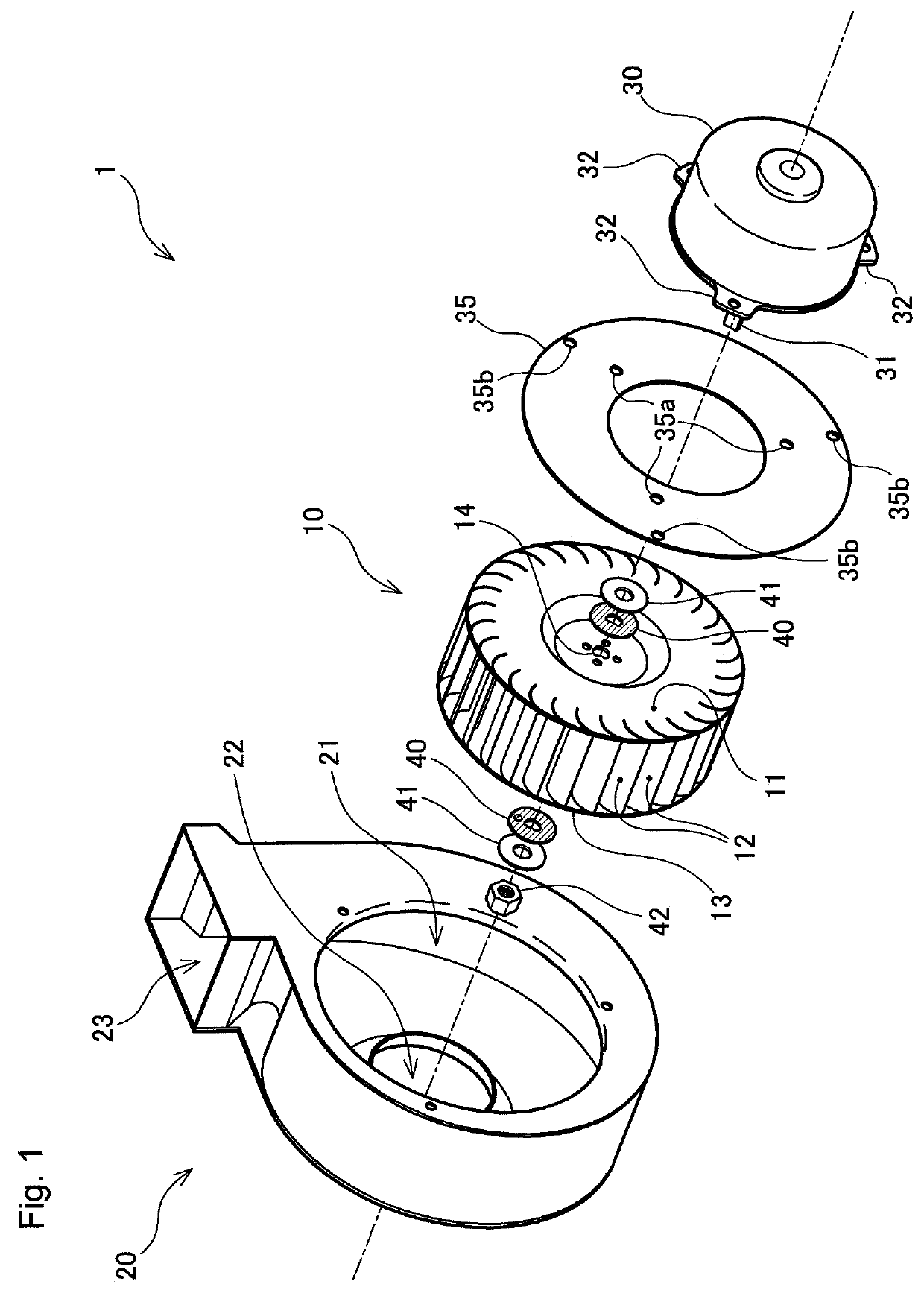
[0027]FIG. 1 is an exploded view of a blower fan 1 according to one embodiment showing its main components. As shown in the figure, the blower fan 1 according to the present embodiment includes an impeller 10 that is rotated to blow air, a fan case 20 accommodating the impeller 10, a motor 30 to rotate the impeller 10, and a fixing plate 35 for fixing the motor 30 to the fan case 20.

[0028]The impeller 10, which is a sirocco fan, includes a substantially disk-shaped rotatable disk 11, a plurality of blades 12 each having one end attached to the periphery of the rotatable disk 11, and an annular coupling plate 13 coupling the other ends of the blades 12. The rotatable disk 11 has a mount hole 14 at the rotation center of the impeller 10. Although the impeller 10 is a sirocco fan in the present embodiment, the impeller 10 may be any other type of impeller, such as a propeller fan.

[0029]The fan case 20, which is an assembly of metal plates, has a circular opening 21 with a diameter larg...


PUM


Abstract

A rotational shaft is placed through insertion holes of rubber washers sandwiching a portion of an impeller having a mount hole. The impeller is mounted on the rotational shaft with a nut on a threaded distal end portion of the rotational shaft. The rotational shaft of the motor includes a locking surface. The insertion holes of the rubber washers each have the same shape as the cross-sectional shape of the rotational shaft. The mount hole of the impeller includes a spacing portion extending at an angle from the linear portion of the insertion hole of each rubber washer away from the locking surface of the rotational shaft. Although the impeller rotates with respect to the rotational shaft under a frictional force applied from the nut tightened against the rotational shaft, this structure prevents metallic contact between the impeller at the mount hole and the locking surface of the rotational shaft.

Description

BACKGROUND OF INVENTIONField of the Invention[0001]The present invention relates to a blower fan that blows air by rotating an impeller using a motor.Background Art[0002]Blower fans are used widely for blowing air with an impeller rotated by a motor. An impeller of a blower fan can be decentered from a rotational shaft of a motor and cause vibration and noise, and thus is to be centered when mounted on the rotational shaft of the motor. In many blower fans, an impeller is mounted on a rotational shaft of a motor in the manner described below.[0003]The rotational shaft of the motor is processed to have a threaded portion at its distal end. The rotational shaft of the motor further has, within a predetermined length from the distal end, a portion with a D-shaped cross section that is formed by processing the peripheral surface of the rotational shaft to be flat in one direction. The impeller has, at the rotation center, a mount hole that is also D-shaped. The mount hole is sized to fi...

Claims


Application Information

Patent Timeline
Patent Type & Authority Patents(United States)
IPC IPC(8): F04D29/26F04D29/66F04D17/16F04D25/08F04D29/60F04D25/06F04D29/054F04D29/62
CPCF04D29/263F04D17/16F04D29/668F04D25/06F04D25/08F04D29/054F04D29/601F04D29/626F16D2300/22F04D29/282
Inventor TAKI, HIROTOSHI
Owner RINNAI CORP
Why Eureka
Try Eureka