Tool jig and method of use

a tool jig and tool technology, applied in drill jigs, weapon components, weapons, etc., can solve the problems of poor prior art techniques in finishing receivers, difficult to achieve quality of results,

Active Publication Date: 2021-09-14
VINROE JORDAN J
View PDF4 Cites 2 Cited by
  • Summary
  • Abstract
  • Description
  • Claims
  • Application Information

AI Technical Summary

Benefits of technology

[0018]The tool jig also has various holes pre-drilled which are fashioned such as to emulate the machining and drill holes that would be necessary to finalize the firearm receiver to work with the factory parts that are commonly available other than the firearm receiver itself. Such parts would readily attach to the receiver completed using the invention thereby allowing a complete firearm to be constructed.

Problems solved by technology

The metal-working and completion of a final and acceptable receiver is time consuming and the quality of results may be difficult to achieve without having the proper tooling and experience.
Prior art techniques in finishing a receiver can produce poor results because of the inaccuracies in measuring, drilling and polishing.

Method used


Image

  • Tool jig and method of use
  • Tool jig and method of use
  • Tool jig and method of use

Examples


Embodiment Construction

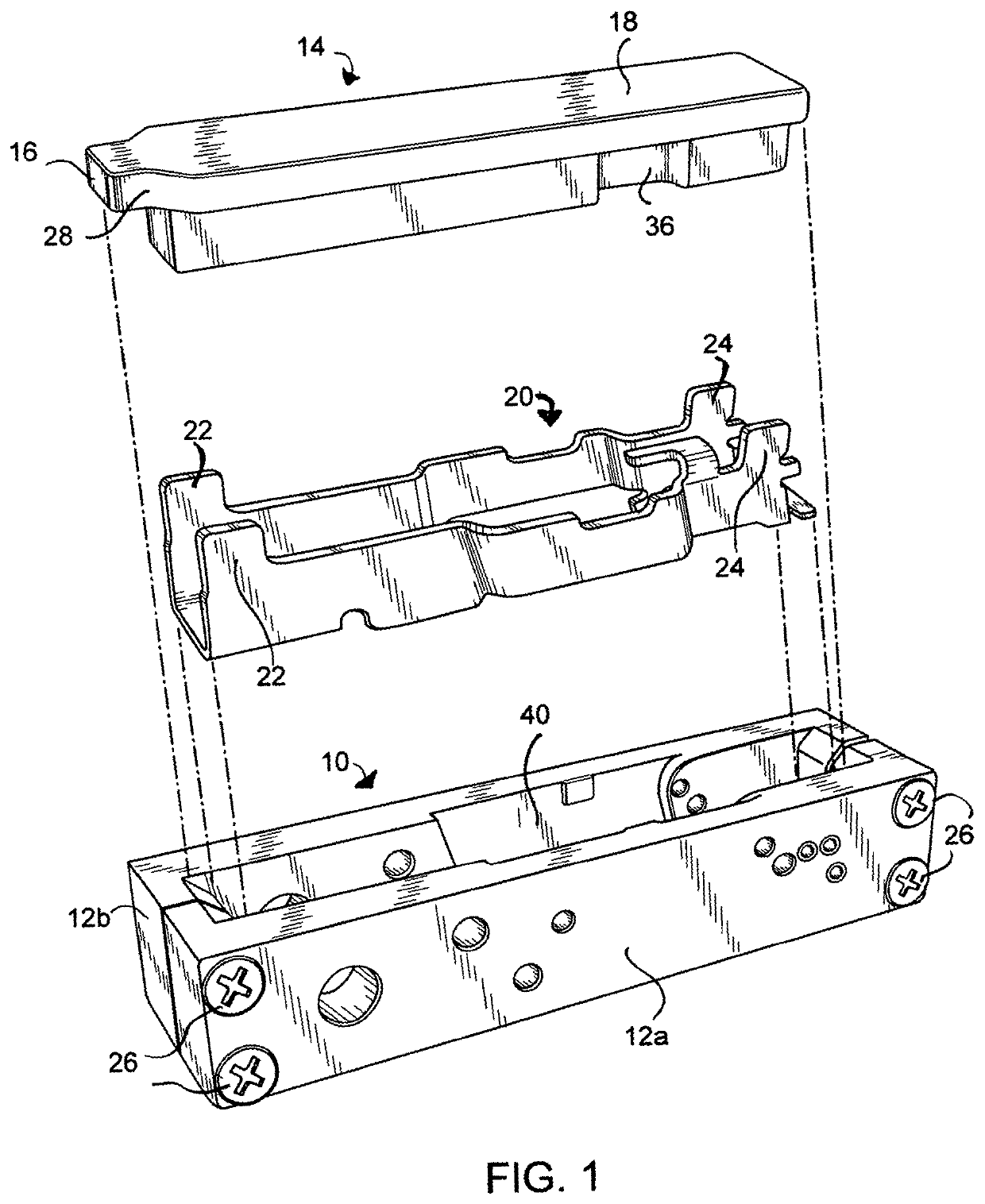
[0025]Turning now to FIG. 1, tool jig 10 is described in an exploded view showing main jig body 12a and 12b mated together for the insertion of receiver 20. Jig top plate 14 is sized to fit within opening 40 designed for receiver 20 to be dropped into for working the receiver as will be described below. Main jig body 12a and 12b are mated together using screws 26 to mate the halves forming jig receiver opening 40 shown in FIG. 1.

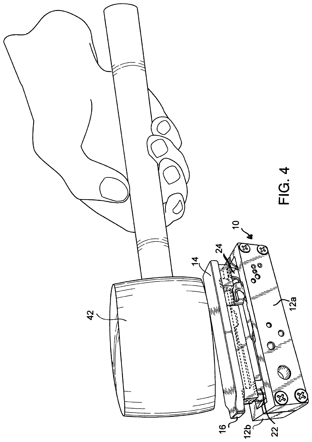
[0026]Once receiver 20 is dropped into receiver opening 40 within jig 10, jig 10 can be placed into a vice to stabilize its position and hold it fast. The jig top plate 14 includes jig forming nose 16 shown in FIG. 1. This top plate 14 is used to assist in forming front receiver rails 22 and rear receiver rails 24 by assisting in bending them outward once receiver 20 is placed in opening 40. As shown in FIG. 4, front receiver rails 22 and rear receiver rails 24 extend outward from jig receiver opening 40 and need to be bent orthogonally, outwardly by physica...


PUM

PropertyMeasurementUnit
volumeaaaaaaaaaa
impulse energyaaaaaaaaaa
areaaaaaaaaaaa

Abstract

A custom-made tool used to control the location and/or movement of parts to be worked to complete an unfinished metal structure into a completed firearm receiver. The tool is a two-part jig fashioned especially for building a handgun receiver from a pre-shaped metal works without the need for other industrial tools or apparatus. Using only commonly available tools in most home work shops, the disclosed jig facilitates producing a firearm receiver from an unfinished metal structure. This disclosure also teaches a method for creating a completed pistol receiver from an unfinished metal structure using the invention.

Description

CROSS REFERENCE TO RELATED APPLICATIONS[0001]This application claims the benefit of Applicant's provisional patent application Ser. No. 62 / 766,518 filed Oct. 23, 2018, entitled A Tool Jig & Method of Building a Handgun Receiver.BACKGROUND OF THE INVENTION1. Field of the Invention[0002]This invention relates to a specialized tool jig, and in particular a metal forming jig used to provide repeatability, accuracy, and interchangeability in the manufacturing of specific firearm-type metal workings.2. Background Art[0003]Many firearms enthusiasts would like to build their own legal, custom-tailored pistol for lawful purposes. It is known by those skilled in the field that a custom, preformed and partially manufactured metallic structure provides an inexpensive way for a firearm enthusiast to legally form and complete their own custom pistol similar to a product that is available on the market by using other preformed or manufactured parts that can be separately obtained on the market. In...

Claims


Application Information

Patent Timeline
Patent Type & Authority Patents(United States)
IPC IPC(8): B23B47/28B23B35/00F41A3/66
CPCB23B47/28B23B35/00F41A3/66B23B2215/28F41A35/00
Inventor VINROE, JORDAN J.
Owner VINROE JORDAN J
Why Eureka
Try Eureka