
Ultrasound probe with an integrated needle assembly and a computer program product, a method and a system for providing a path for inserting a needle of the ultrasound probe

a technology of ultrasound probe and integrated needle, which is applied in the field of ultrasonic wave application, can solve the problems of increasing the cost, reducing the success rate of lumbar puncture, and obstructing or blinding needle insertion, and increasing the cos

Active Publication Date: 2021-09-28
DANDELION TECH LLC
View PDF15 Cites 6 Cited by
  • Summary
  • Abstract
  • Description
  • Claims
  • Application Information

AI Technical Summary

Benefits of technology

[0006]An object of the present invention is to provide a device having an ultrasound probe housing, a guide channel cut-out or aperture, and a needle guide assembly. The ultrasound probe housing generates ultrasound waves to produce images inside of the body of a patient. The ultrasound probe housing has an ambient side and a body side and can be of any shape meeting the requirements of the invention. The ultrasound probe housing may also provide an adhesion or suction quality to the body side of the device to facilitate aspects of the invention.
[0015]Another object of the invention is to provide the step of guiding the needle on the provided path to the target internal body part using a needle insertion handle provided on the needle through the rotatable needle guide assembly, wherein the needle being covered in the field of view of the ultrasound probe is displayed on a display device during insertion, and wherein the needle insertion handle provides enhanced maneuverability for the practitioner / user.
[0017]An object of the present invention is to provide a device having an ultrasound probe housing. The ultrasound probe housing generates ultrasound waves to produce images inside of the body of a patient. The ultrasound probe housing has an ambient side and a body side. The ultrasound probe housing provides an adhesion or suction quality to the body side of the device.

Problems solved by technology

Failure rate of one of the most common medical procedures, lumbar puncture, however, is about 20% owing to the difficulty of identifying landmarks and the inability to visualize the location and trajectory of the needle.
While ultrasound has been used to aid in the identification of structural landmarks, needle insertion continues to be an obstructed or blind procedure without significant improvement in success rates with using static ultrasound.
Failure of a bedside lumbar puncture consequently leads to a fluoroscopic lumbar puncture which results in increased cost, unnecessary inpatient admissions and delay in patient care.
These procedures can use either landmarks or are limited to two-dimensional (2D) ultrasound, which limits the number of providers choosing this method due to the high initial skill required for a successful procedure.
But each approach continues to have multiple system or use limitations.
These devices, however, are limited in function at least by the location or attachment of the needle away from the ultrasound transducer itself such that the needle is outside of the field of view provided by the ultrasound transducers.
Other devices provide a needle that has restricted movement yielding inadequate procedural flexibility.
Additionally, other certain available devices provide inadequate image viewing, such as with 2D imaging, that make needle tracking or visualization more difficult for the medical practitioner.
These systems also suffer from the inability to provide a predicted optimum path within the patient for needle travel.
Obstructed image viewing of the needs path and inability to predict the path of the needle leads to procedure failure.
Overall, there remains an enhanced risk of injuring the anatomical parts of the body such as the tissues, nerves etc. that are located near the target internal body part.

Method used


Image

  • Ultrasound probe with an integrated needle assembly and a computer program product, a method and a system for providing a path for inserting a needle of the ultrasound probe
  • Ultrasound probe with an integrated needle assembly and a computer program product, a method and a system for providing a path for inserting a needle of the ultrasound probe
  • Ultrasound probe with an integrated needle assembly and a computer program product, a method and a system for providing a path for inserting a needle of the ultrasound probe

Examples


Embodiment Construction

[0044]While various embodiments of the present disclosure are provided herein, it should be understood that they are presented as examples only, and are not intended to be limiting. Similarly, the drawings and diagrams depict structural or architectural examples or alternate configurations of the invention, which are provided to aid in understanding the features and functionality of the various embodiments of the invention but are not intended to be limiting. The embodiments and features may be implemented and / or altered in a variety of ways known to those of ordinary skill the art.

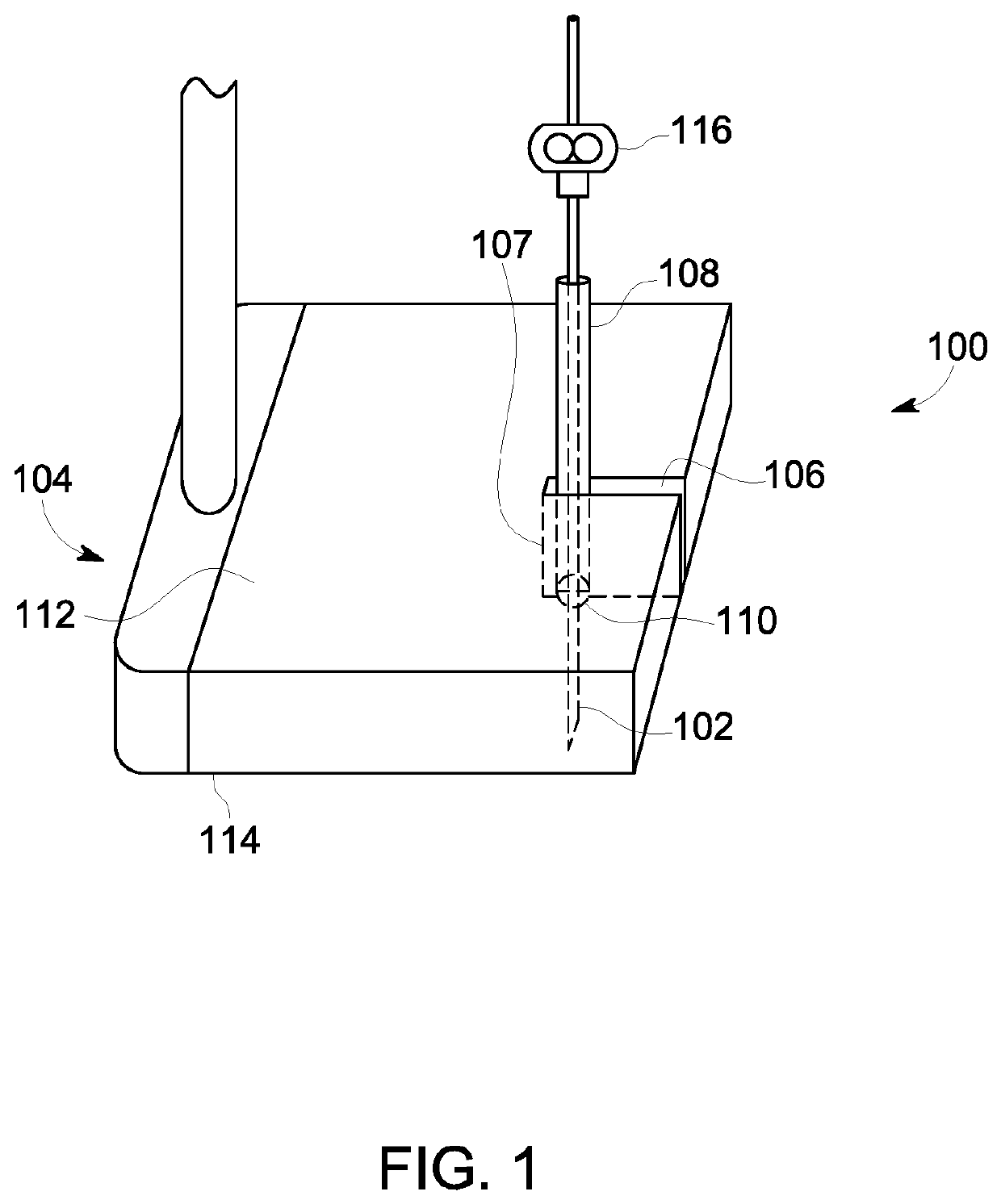
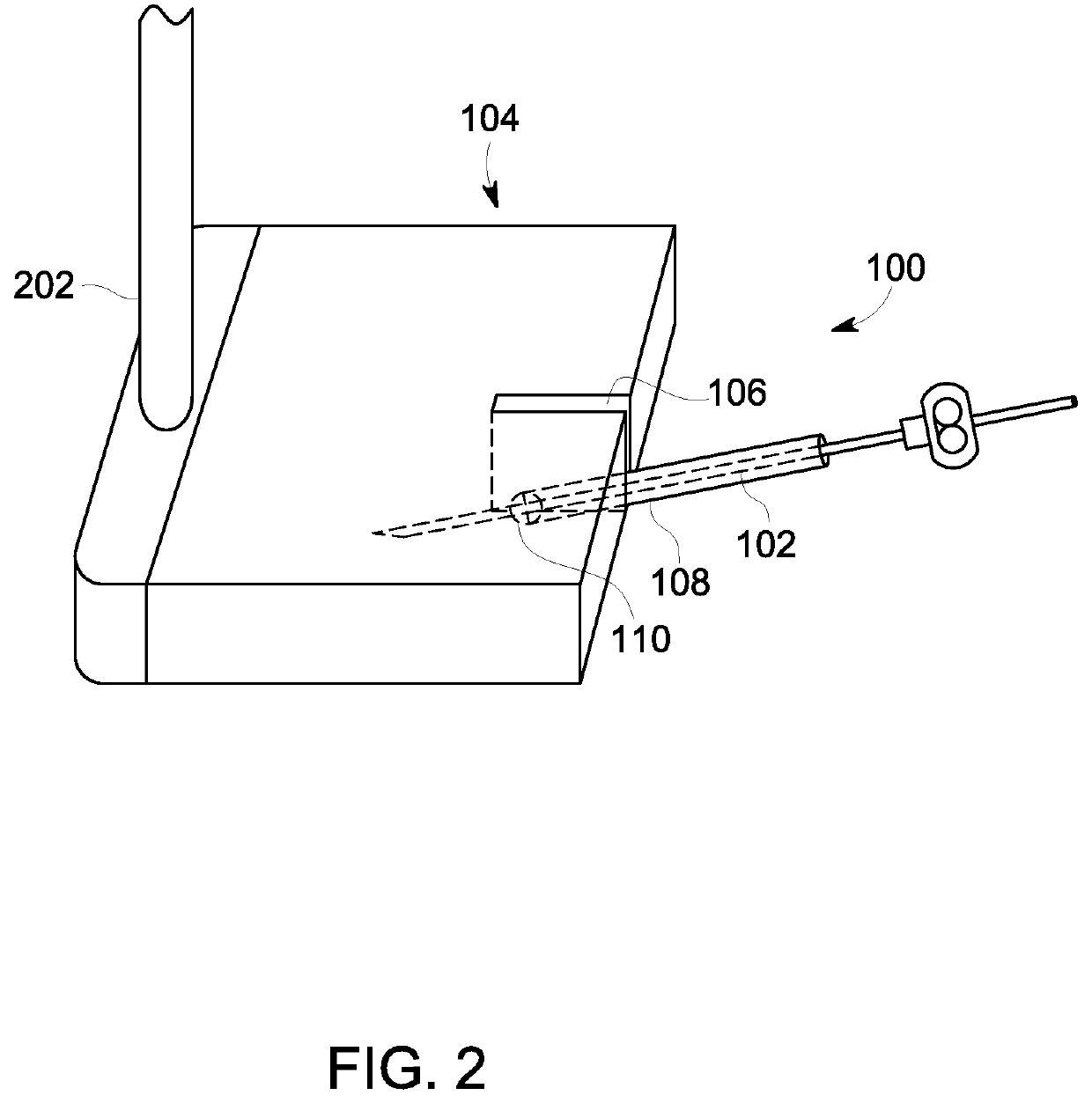
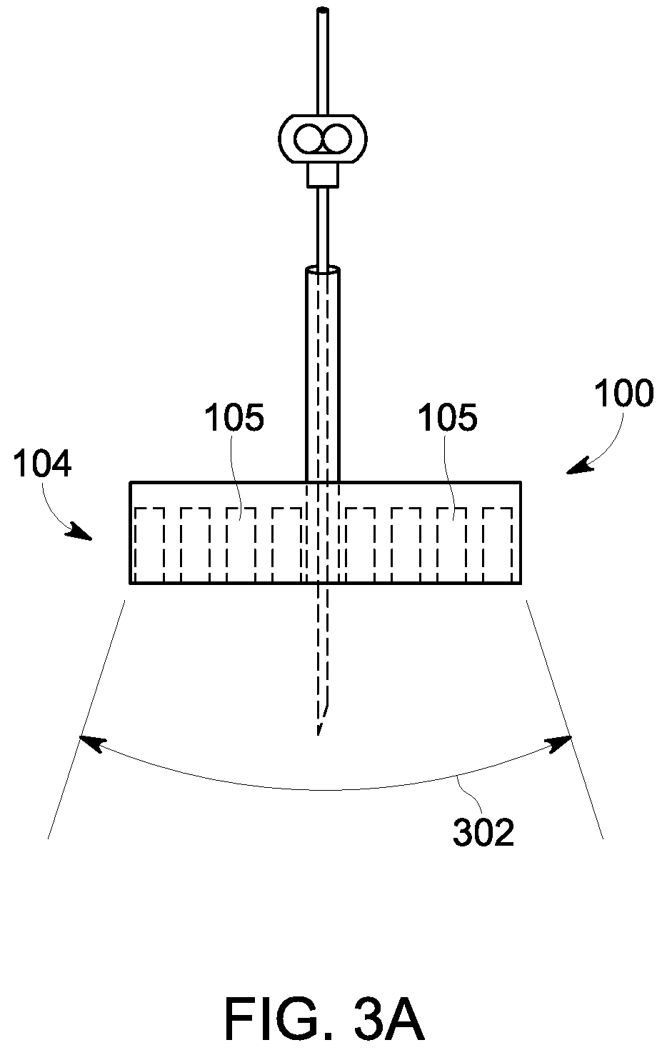
[0045]FIG. 1 illustrates a perspective view of a device 100 providing a path for inserting a needle 102 for performing medical procedures, in accordance with an embodiment of the present invention. The device 100 includes an ultrasound probe housing 104, a guide channel cut-out or aperture 106, and a needle guide assembly 108. In another embodiment of the present invention, the device 100 further includes...


PUM


Abstract

A device and system for and methods of using an ultrasound probe housing containing ultrasound probes configured to produce images inside the body of a patient for procedures requiring needle or probe insertion. The ultrasound probe housing can be configured with a guide channel cut-out or aperture between the ambient side and body side of a patient. A needle guide assembly may pivotally connect internal to the guide channel cut-out or aperture of the ultrasound probe housing at a pivot point such that during use the needle enters the patient through the needle guide assembly within the ultrasonic probe housing so that the needle can be visualized by the ultrasonic probes in real time. The ultrasound probe housing may also provide an adhesion or suction quality to the body side of the device to facilitate aspects of the invention.

Description

FIELD OF THE INVENTION[0001]Embodiments of the present invention generally relate to application of ultrasonic waves in medical procedures and more particularly to an ultrasound probe with an integrated needle assembly and a computer program product, a method and a system for providing a path for inserting a needle of the ultrasound probe.BACKGROUND ART[0002]Procedures that require needle penetration are some of the most common medical procedures, yet remain relatively unchanged since their inception in 1891. In a typical scenario, a practitioner uses palpation of landmarks, such as the iliac crests and the spinous processes, to guide location of a needle during a blind procedure. Examples of such procedures include lumbar puncture (LP), epidural and spinal injections, and spinal nerve blocks. Failure rate of one of the most common medical procedures, lumbar puncture, however, is about 20% owing to the difficulty of identifying landmarks and the inability to visualize the location a...

Claims


Application Information

Patent Timeline
Patent Type & Authority Patents(United States)
IPC IPC(8): A61B8/08A61B8/00
CPCA61B8/0841A61B8/4254A61B8/4444A61B8/483A61B8/5253A61B8/5246A61B17/3403A61B2090/034A61B2090/067A61B2090/0811A61B2017/00017A61B2017/00398A61B2017/00951A61B2017/3413A61B2017/308A61B2017/3407A61B2017/347
Inventor ADAMS, PAULVETTER, CHRISTOPHER
Owner DANDELION TECH LLC
Learn More