
Method and system for facilitating compression

a compression method and data technology, applied in the field of data compression, can solve the problems of increasing overall costs, wasting energy, giving up in frustration, etc., and achieve the effects of facilitating decompression of the entire n-dimensional space, improving qoe for the receiver, and speeding up downloads

Active Publication Date: 2019-10-22
PRIEDITIS ARMAND
View PDF2 Cites 2 Cited by
  • Summary
  • Abstract
  • Description
  • Claims
  • Application Information

AI Technical Summary

Benefits of technology

The patent describes a method for compressing and transmitting high-definition video over low-bandwidth networks, such as the internet, to improve the quality of experience (QoE) for the receiver. The method involves clustering data to extract relevant information and compress it for transmission. The resulting compression model can be used to compress similar data and then sent to medical professionals for quicker and more accurate diagnoses. The method can also reduce download costs for companies and make it easier to decompress the video for viewing. Additionally, the method can perform multiple compressions to compress an entire space and provide the compressed versions of different patches to the receiver for decompression. Overall, the method improves QoE for the receiver by enabling faster downloads, faster decompression, and higher fidelity decompressions.

Problems solved by technology

QoE heavily impacts revenue on the server side: when bandwidth becomes narrower and content becomes large, QoE becomes worse, which can prompt a client to cancel a service, seek the content from sources with more bandwidth, or simply give up in frustration.
Slow downloads can also eat up energy (e.g., battery power), which can raise overall costs.
For example, images of nature scenes tend to contain a large amount of redundant information because neighbor pixels tend to be correlated with each other.
But these codecs do not leverage particulars of the data being compressed.
But such methods still result in images that are too big to load quickly on mobile devices.
For example, companies that spend enormous amounts of money on infrastructures for image downloads (e.g., Twitter) could see lighter loads on their infrastructure and therefore scale down spending on such infrastructures.

Method used


Image

  • Method and system for facilitating compression
  • Method and system for facilitating compression
  • Method and system for facilitating compression

Examples


Embodiment Construction

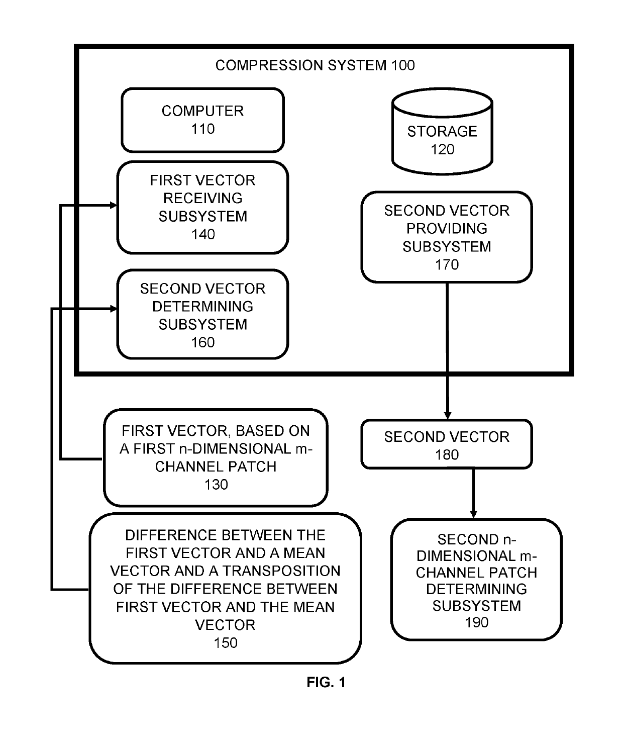
[0031]FIG. 1 shows an example compression system 100 in accordance with an embodiment of the subject matter. Compression system 100 is an example of a system implemented as a computer program on one or more computers in one or more locations (shown collectively as computer 110), with one or more storage devices in one or more locations (shown collectively as storage 120), in which the systems, components, and techniques described below can be implemented.

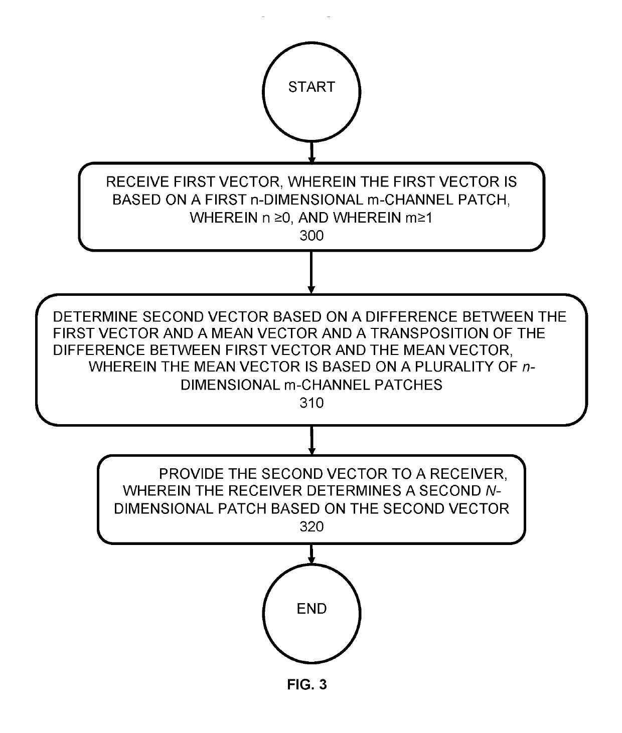
[0032]Compression system 100 receives first vector 130, which is based on a first n-dimensional m-channel patch. The first vector can be a flattened version of the elements of the first n-dimensional m-channel patch. Here “flattening” means that all the elements of the patch are flattened into a vector. For example, in an image, the first vector can comprise a 27-element vector, which comprises the RGB values of a flattened 3×3 patch. Similar flattening can be applied to any first n-dimensional m-channel patch. The result is a vecto...


PUM


Abstract

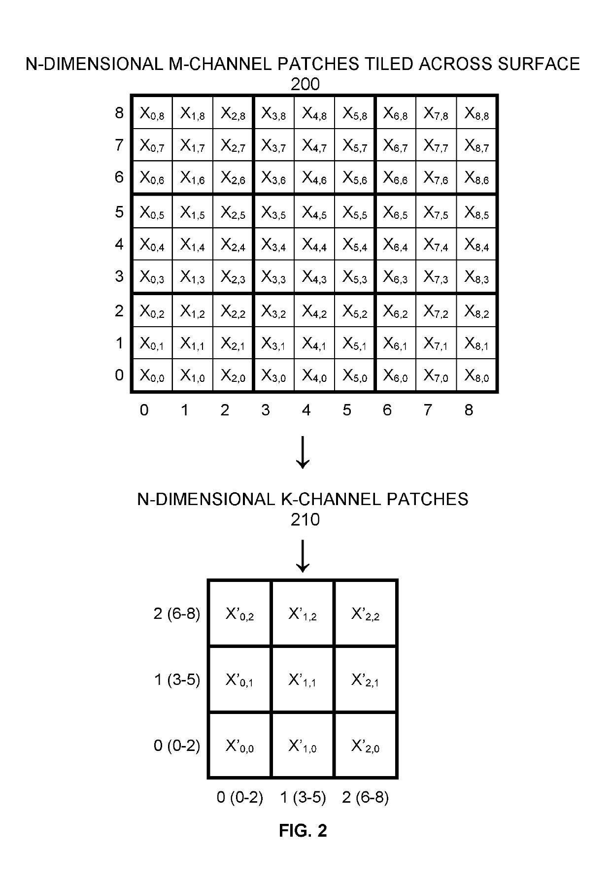
During operation, embodiments of the subject matter can perform compression of an n-dimensional m-channel patch based on unsupervised learning (clustering). Embodiments of the subject matter can perform multiple such compressions of patches tessellated (tiled) across a space. Embodiments of the subject matter can also perform hierarchical compression through recursive application of embodiments of the subject matter. Embodiments of the subject matter can compress but are not limited to compressing the following: a database, a sequence, an image, a video, and a volumetric video.

Description

BACKGROUNDField[0001]The subject matter relates to data compression, where the data can be a database, a table, a sequence, an image, a video, or any multi-dimensional shape comprised of elements that are vectors (channels). For example, each pixel element in an image can comprise a three-element vector, which can correspond to the RGB channels.Related Art[0002]Internet video streaming and downloads have exploded the last few years. This growth is not likely to stop: video traffic is expected to quadruple in the next five years. In addition, the Big Data revolution resulted in enormous and diverse data sets including but not limited to images, texts, audio, genomic data, 3D virtual reality data, medical volumetric video data, and point cloud data from autonomous mapping. This growth is driving further refinements in compression to ensure Quality of Experience (QoE) on the client (receiver) side.[0003]QoE comprises three parts: speed of compressed content delivery from the server to ...

Claims


Application Information

Patent Timeline
IPC IPC(8): H03M7/30G06F17/16G06F17/18G06N20/00G06N7/00
CPCH03M7/3082G06N20/00G06N7/00G06F17/16G06F17/18H03M7/3079G06N7/01
Inventor PRIEDITIS, ARMAND
Owner PRIEDITIS ARMAND
Learn More