Device, system and method for CO2 monitoring

a co2 monitoring and co2 technology, applied in the field of devices, systems and methods for co2 monitoring, can solve the problems of expensive sensors, and achieve the effect of reducing costs and increasing co2 volum

Active Publication Date: 2021-10-05
KONINKLJIJKE PHILIPS NV
View PDF21 Cites 0 Cited by
  • Summary
  • Abstract
  • Description
  • Claims
  • Application Information

AI Technical Summary

Benefits of technology

[0027]It is an object of the present invention to provide a device, system and method for CO2 monitoring and particularly detecting an increase in CO2 volume at lower costs, wherein the device and system may preferably be usable for more than one purpose.
[0046]In another embodiment said breathing monitor is configured to separately determine one or more breathing parameters for two or more subjects present in the monitored area and to identify changes of one or more breathing parameters for the two or more subjects separately. The CO2 estimation unit is then configured to estimate the absolute CO2 level based on the identified changes of one or more breathing parameters for the two or more subjects. Hence, by use of the present invention the breathing parameters for multiple persons can be determined separately, which can be used together for determining the CO2 level at an increased accuracy.
[0047]The breathing monitor may also be configured to identify changes of the one or more breathing parameters for the two or more subjects with respect to a baseline for the respective breathing parameter, in particular with respect to a common baseline for two or more subjects or with respect to individual baselines for one or more subjects. This further increases the CO2 level estimation.
[0048]In another embodiment the breathing monitor may be configured to identify changes of the breathing rate per subject and the CO2 estimation unit may be configured to determine, if the breathing rate and / or its change rate exceed a respective threshold for two or more subjects, that the CO2 level has exceeded a CO2 level threshold. This provides a simple but effective way of estimating the CO2 level.
[0050]Preferably, the signal input is configured to obtain supplementary data including one or more of air quality data, environmental data, subject behavior data, and sensor data, wherein said breathing monitor is configured to identify changes of the one or more breathing parameters for an individual subject, in particular with respect to a baseline, from the obtained one or more monitoring signals and the obtained supplementary data. This leads to an increased accuracy of the CO2 level estimation.

Problems solved by technology

There are several limitations of this approach however: first, such sensors may be costly (although in recent years the price is dropping significantly), and second they are useful only for one function, namely for measuring the CO2 level.

Method used


Image

  • Device, system and method for CO2 monitoring
  • Device, system and method for CO2 monitoring
  • Device, system and method for CO2 monitoring

Examples


first embodiment

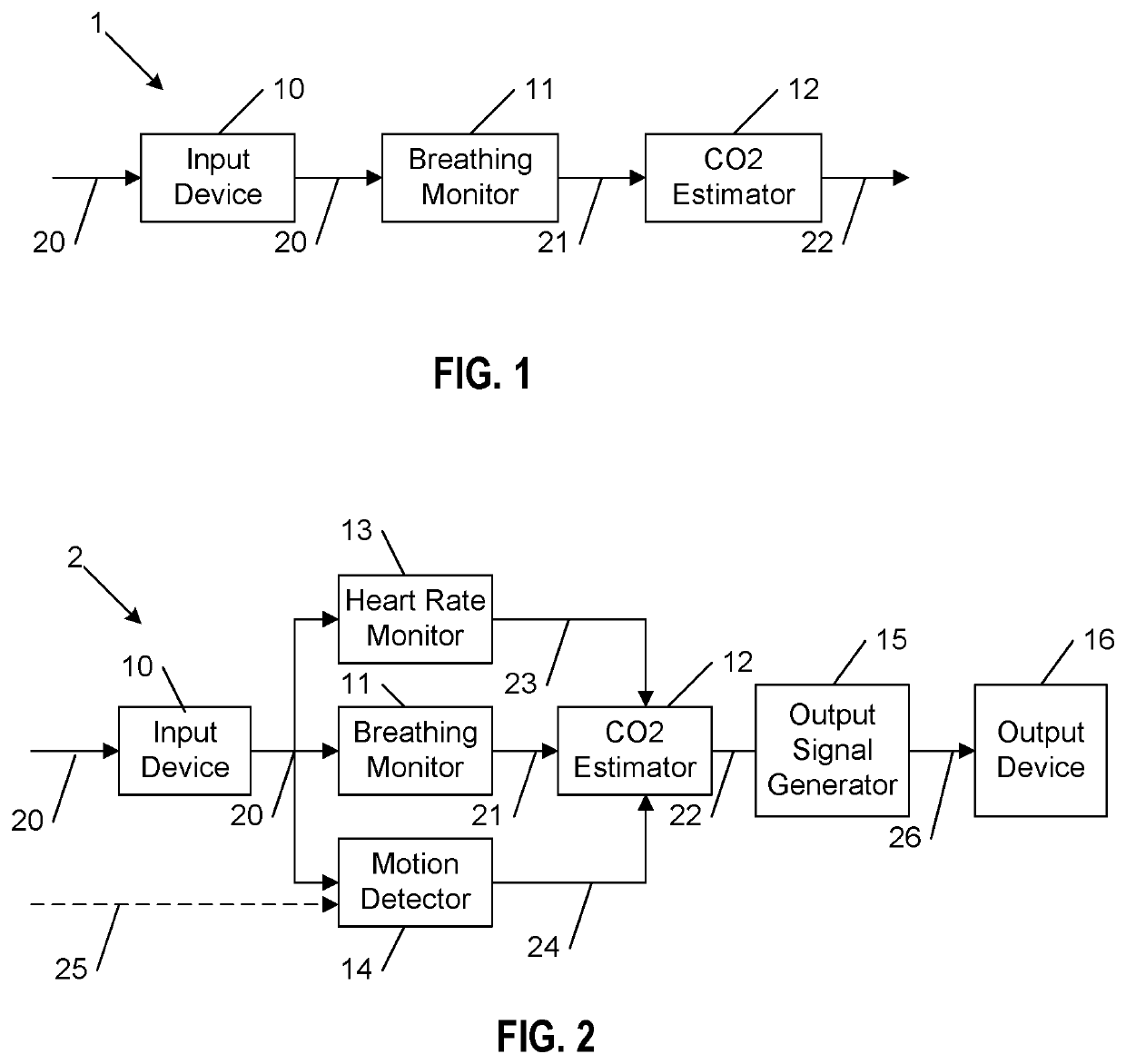
[0062]FIG. 1 shows a schematic diagram of a device 1 according to the present invention. The device 1 comprises a signal input 10 for obtaining one or more monitoring signals 20 of a monitored area, a breathing monitor 11 for determining one or more breathing parameters 21 of one or more subjects present in the monitored area from the obtained one or more monitoring signals, and a CO2 estimation unit 12 for estimating the CO2 level 22 in the monitored area based on the determined one or more breathing parameters.

[0063]The device 1 may generally be implemented in hard- and / or software, e.g. as a processor, computer or application program (“app”) running on a user device, such as a smartphone, that is programmed accordingly.

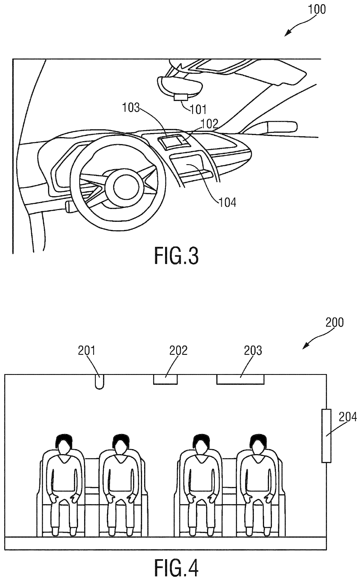
[0064]One main application of the present invention may be in vehicles, such as cars and buses. A car can be considered a confined environment, provided that the ventilation system of the car controls the fresh air intake (from outside). Nowadays cars are equipped ...

second embodiment

[0070]FIG. 2 shows a schematic diagram of a device 2 according to the present invention. In this embodiment one or more further elements may be provided.

[0071]In one implementation the device 2 may further comprise a heart rate monitor 13 for determining heart rate 23 of the one or more subjects, wherein the CO2 estimation unit 11 is configured to estimate the CO2 level in the monitored area based on the determined one or more breathing parameters and the determined heart rate and / or changes of heart rate over time. The heart rate monitor 13 may be configured to detect the heart rate from the monitoring signals 20, e.g. by use of the PPG technique. Alternatively, other means for determining the heart rate may be provided, e.g. by use of a dedicated heart rate sensor, such as a pulse oximeter.

[0072]In another implementation the device 2 may further comprise a motion detector 14 for detecting physical motion 24 of a subject, wherein said CO2 estimation unit 12 is configured to ignore ...

third embodiment

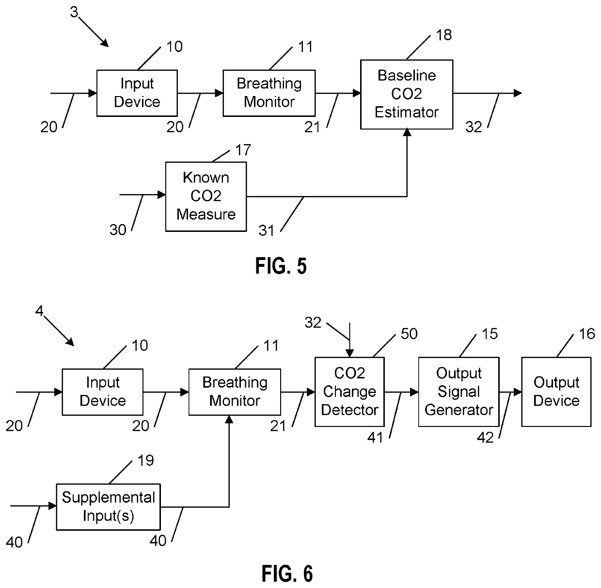
[0085]FIG. 5 shows a schematic diagram of a device 3 according to the present invention. The device 3 may be used to obtain a baseline or baseline model 32 for the subject's breathing rate changes due to CO2 level changes. The baseline or baseline model 32 can be determined at predetermined or irregular intervals, e.g. every year or every month and may then be used by the device to determine the actual CO2 level. Also, the baseline may be may be obtained by performing measurements for an initial period, for example ten to fifteen minutes and taking an average of the measurements as the baseline. The average could be an arithmetic mean, a median or a modal value. It is better that the initial period occur close to when the people enter the monitored space after it has been un- or lightly occupied for a while since the CO2 levels should, in theory, be close to the natural background levels.

[0086]In addition to the elements of the device 1 shown in FIG. 1, the device 3 further comprise...


PUM


Abstract

The present invention relates to a device, system and method for CO2 monitoring. To enable continuous monitoring at low cost and in a simple manner, the device comprises a signal input (10) for obtaining one or more monitoring signals (20) of a monitored area, a breathing monitor (11) for determining one or more breathing parameters (21) of one or more subjects present in the monitored area from the obtained one or more monitoring signals, and a CO2 estimation unit (12) for estimating the CO2 level (22) in the monitored area based on the determined one or more breathing parameters.

Description

CROSS-REFERENCE TO PRIOR APPLICATIONS[0001]This application is the U.S. National Phase application under 35 U.S.C. § 371 of International Application No. PCT / EP2017 / 077551, filed on 27 Oct. 2017, which claims the benefit of European Patent Application No. 16196883.9, filed on 2 Nov. 2016. These applications are hereby incorporated by reference herein.FIELD OF THE INVENTION[0002]The present invention relates to a device, system and method for CO2 monitoring. Further, the present invention relates to a vehicle comprising such a device.BACKGROUND OF THE INVENTION[0003]Normal dry air, at standard temperature and pressure (STP) of 101.325 kPa and 0° C., consists of (expressed in volume) 20.95 percent oxygen, 78.08 percent nitrogen, 0.0314 percent carbon dioxide, 0.93 percent argon and trace amounts of 14 other gases. Assuming that the oxygen content of the air is normal, the following figures are typical for confined rooms with very restricted airflow, such as underground mines:[0004]Nor...

Claims


Application Information

Patent Timeline
Patent Type & Authority Patents(United States)
IPC IPC(8): B60H1/00A61B5/0205A61B5/11A61B5/00A61B5/024A61B5/08A61B5/083A61B5/091
CPCB60H1/008A61B5/0205A61B5/1118A61B5/486B60H1/00742A61B5/02405A61B5/0816A61B5/0836A61B5/091A61B2560/0247A61B5/0077A61B5/02416A61B5/681A61B2503/22F24F2110/70
Inventor DEN BRINKER, ALBERTUS CORNELISJEANNE, VINCENTASSELMAN, MICHEL JOZEF AGNESKARAKAYA, KORAYKERSTEN, GERRIT MARIATIEMANN, CHRISTIAN ANDREASBULUT, MURTAZA
Owner KONINKLJIJKE PHILIPS NV
Why Eureka
Try Eureka