
Isotropic and all-optical scalar magnetometer for measuring an ambient magnetic field

a scalar magnetometer and ambient magnetic field technology, applied in the direction of magnetic resonance measurement, etc., can solve the problems of crosstalk between adjacent magnetometers, bulky solution, and sensitive to gradients

Active Publication Date: 2021-10-12
COMMISSARIAT A LENERGIE ATOMIQUE ET AUX ENERGIES ALTERNATIVES
View PDF13 Cites 0 Cited by
  • Summary
  • Abstract
  • Description
  • Claims
  • Application Information

AI Technical Summary

Problems solved by technology

This solution is however bulky and sensitive to gradients.
However, these coils contribute to the bulk of the magnetometer and may cause crosstalk between adjacent magnetometers, for example in the case where a plurality of magnetometers are used to form a gradiometer.
This solution therefore requires three optical accesses in order to ensure isotropy of the measurement, which proves to be bulky.
However, this configuration does not make it possible to use the control scheme of the patent EP 0 579 537 B1 presented above for providing isotropy of the sensor.
However, the angle at which this condition is satisfied varies according to several experimental parameters and this architecture in general exhibits a non-optimal signal to noise ratio since the change in sign of the signal LA1 does not correspond to the maximum of the signal LA2.

Method used


Image

  • Isotropic and all-optical scalar magnetometer for measuring an ambient magnetic field
  • Isotropic and all-optical scalar magnetometer for measuring an ambient magnetic field
  • Isotropic and all-optical scalar magnetometer for measuring an ambient magnetic field

Examples


first embodiment

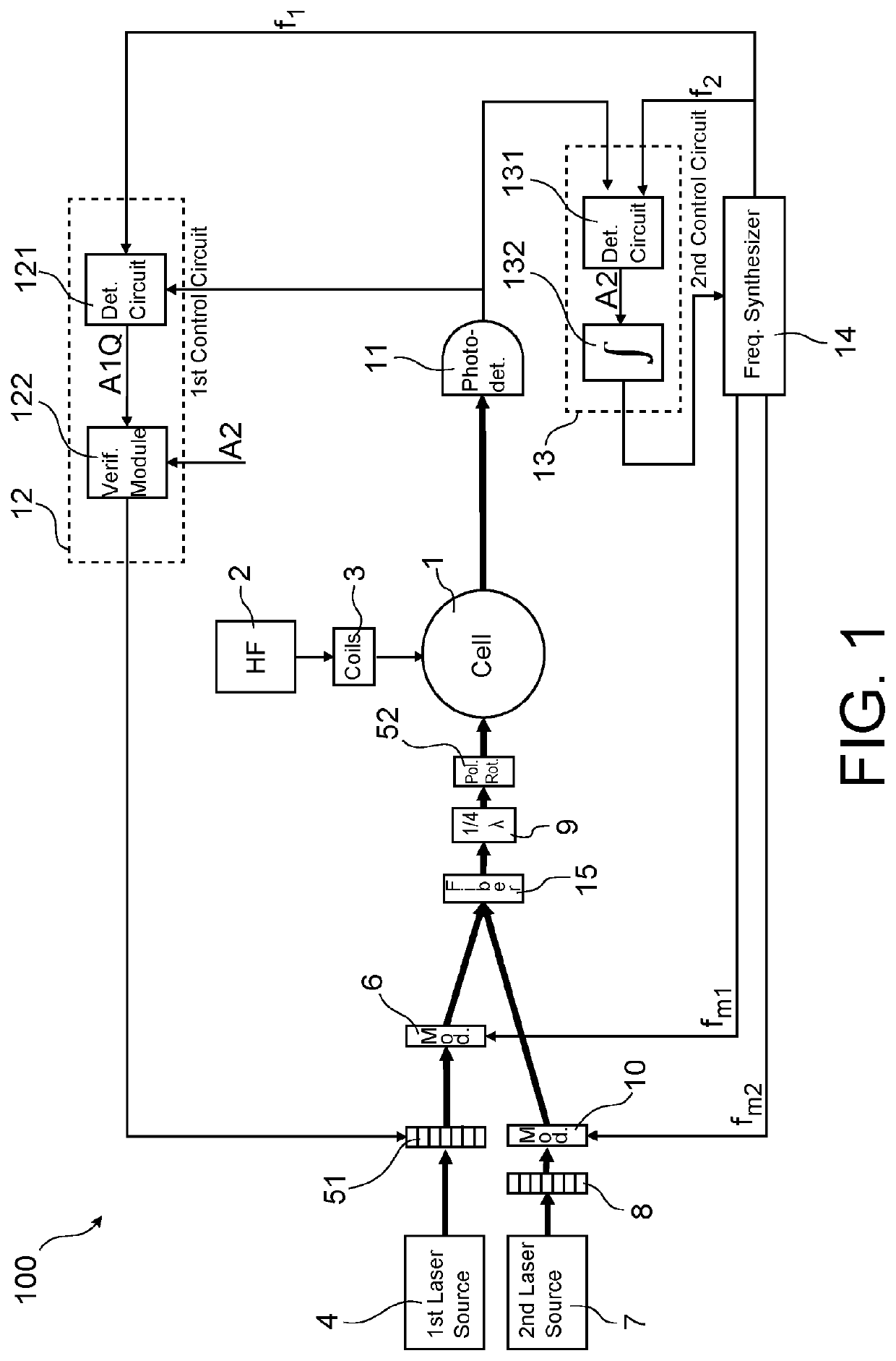
[0056]In a first embodiment shown schematically in FIG. 1, said means for illuminating the cell comprise an assembly of linear polarisation maintenance fibres 15 in which the pump beam and the AC Stark effect beam are injected and a collimator at the output of said assembly for collimating the pump beam and the AC Stark effect beam in the direction of the cell.

[0057]In an assembly of fibres, one end of each of the fibres is bared and is assembled with the ends of the other fibres in a ferrule, for example a part with V-shaped grooves. Thus the propagation directions of all the beams are fixed. At the output of the assembly, the beams can be collimated by a common lens (which is possible given the very small separation between the fibres in the assembly of fibres, typically 100 μm) in order to cover the entire cell.

[0058]Since the fibres are of the polarisation maintenance type, relative polarisation directions can be fixed. It is possible in particular to provide that, in said assem...

second embodiment

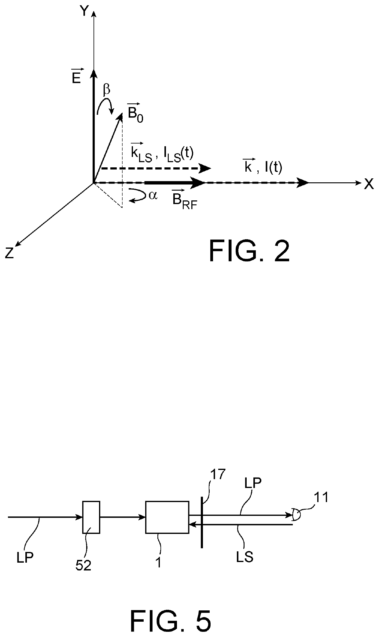
[0059]In a second embodiment shown schematically in FIG. 5, the pump and AC Stark effect beams propagate in opposite directions in the cell. In this way, only the pump beam is photodetected and the signal to noise ratio is increased.

[0060]In this second embodiment, the modulated and linearly polarised pump beam FP is injected into a linear polarisation maintenance fibre. A collimator is arranged at the output of said fibre in order to collimate the pump beam in the direction of the polarisation rotator 52 upstream of the cell 1. The pump beam at the output of the cell is collected by the photodetector 11.

[0061]The AC Stark effect beam LS is also injected into a linear polarisation maintenance fibre. A collimator is arranged at the output of said fibre in order to collimate the AC Stark effect beam in the direction of a quarter-wave plate 17 here arranged downstream of the cell. The pump beam and the AC Stark effect beam may have propagation directions in the cell forming between the...


PUM


Abstract

An optical-pumping magnetometer intended to measure an ambient magnetic field. It comprises: an arrangement for illuminating a cell filled with an atomic gas with a pump beam and an AC Stark effect beam propagating collinearly or almost collinearly in the cell, the pump beam being tuned to an atomic transition line, modulated by a first modulator by way of a first modulation frequency (fm1) and polarised linearly in a polarisation direction that can be turned by a polarisation rotator, the AC Stark effect beam being offset from the atomic transition line, modulated by a second modulator by way of a second modulation frequency (fm2) and polarised circularly, a first control circuit acting on the polarisation rotator in order to keep a constant angle (β) between the polarisation direction of the pump beam and the ambient magnetic field, a second control circuit acting on the first and second modulator in order to keep the first and second modulation frequency at the Larmor frequency of the atomic gas or at one of the harmonics thereof.

Description

CROSS-REFERENCE TO RELATED APPLICATIONS[0001]This application claims priority from French Patent Application No. 1902087 filed on Feb. 28, 2019. The content of this application is incorporated herein by reference in its entirety.TECHNICAL FIELD[0002]The field of the invention is that of optical-pumping scalar magnetometers. The invention relates more particularly to a so-called isotropic magnetometer configuration for which the measurements are not dependent on the relative orientation of the magnetometer with respect to the magnetic field to be measured.PRIOR ART[0003]Optical-pumping magnetometers use atomic gases confined in a cell, typically metastable helium or alkaline gases, as a sensitive element. These magnetometers, which may adopt various configurations, make it possible to determine the magnetic field by using the following three processes, which take place either sequentially or concomitantly:[0004]The use of polarised-light sources, typically lasers, makes it possible t...

Claims


Application Information

Patent Timeline
Patent Type & Authority Patents(United States)
IPC IPC(8): G01R33/26
CPCG01R33/26
Inventor LIEB, GAËTANPALACIOS LALOY, AGUSTIN
Owner COMMISSARIAT A LENERGIE ATOMIQUE ET AUX ENERGIES ALTERNATIVES
Learn More